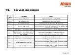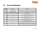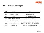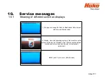
10. Service messages
Sheet 108
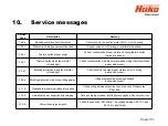
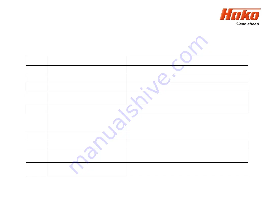
Service-
Code
Description
Remedy
3.2.6.5.
Backup battery weak
Replace backup battery; Type CR2032
3.2.6.6.
Backup battery empty
Replace backup battery; Type CR2032
3.3.1.1.
Service intervall expired
Reset the service intervall with the Hako diagnosis
3.3.1.5.
SD-Card on the Display
re format the SD-card with the diagnosis system, if error repeats, replace
the SD-card with a new one
3.3.6.2.
Group signal low power output overload
Overload of small cosumer outputs (e.g. buzzer, magnetic valve. Etc.)
3.4.1.1.
Malfunction drive control unit; pre selection of
driving direction implausibly or interrupted
wiring accelerator
Check wiring of the accelerator -B03 and direction switch;
Message is generated by the operator panel (-A02)
3.4.1.2.
Malfunction drive control unit front
see blinking code on drive control unit
3.4.1.4.
Malfunction drive control unit rear
see blinking code on drive control unit
3.4.5.1.
over temperature drive motor front
check the wiring of the drive motor thermo switch. Is the machine used
outside it´s specification?
3.4.5.2.
over temperature drive motor rear
check the wiring of the drive motor thermo switch. Is the machine used
outside it´s specification?
Summary of Contents for Scrubmaster B175 R
Page 37: ...3 Technical Data Sheet 37...
Page 38: ...3 Technical Data Sheet 38...
Page 39: ...3 Technical Data Sheet 39...
Page 40: ...3 Technical Data Sheet 40...
Page 41: ...3 Technical Data Sheet 41...
Page 42: ...3 Technical Data Sheet 42...
Page 43: ...3 Technical Data Sheet 43...
Page 44: ...3 Technical Data Sheet 44...
Page 46: ...4 1 Hako System Maintenance customer Sheet 46...
Page 47: ...4 1 Hako System Maintenance customer Sheet 47...
Page 48: ...4 2 Hako System Maintenance I Sheet 48...
Page 49: ...4 2 Hako System Maintenance I Sheet 49...
Page 50: ...4 2 Hako System Maintenance I Sheet 50...
Page 51: ...4 3 Hako System Maintenance II Sheet 51...
Page 52: ...4 4 Hako System Maintenance III S Safety Check Sheet 52...
Page 65: ...6 Machine settings 6 1 6 Charging characteristics for integrated charger Sheet 65...
Page 74: ...7 Mechanical components Figure 7 2a Figure 7 2b Sheet 74 7 1 Squeegee...
Page 76: ...7 Mechanical components Height adjustment Figure 7 4 Sheet 76 7 1 Squeegee...
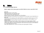
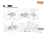
Page 104: ...9 Drive 9 2 4 Steering angle sensor Figure 9 5 180 130 170 150 120 Folie 104...
Page 113: ...11 Battery charger 11 1 Operating manual Sheet 113...
Page 114: ...11 Battery charger Sheet 114 11 1 Operating manual...
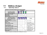
Page 115: ...11 Battery charger Sheet 115 11 1 Operating manual...
Page 116: ...11 Battery charger Sheet 116 11 1 Operating manual...
Page 123: ...13 Notes Sheet 123...
Page 124: ...Sheet 124 13 Notes...

