
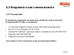
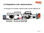
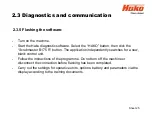


2.3.3 Connection to the diagnostic PC
2.3 Diagnostics and communication
Sheet 22
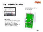
•
Ensure that the
–A01 control unit has been fully installed in the machine before
activating the backup battery. To do this, remove the insulating strip between the
battery (CR2032) and the battery holder on the control unit.
•
Connect the interface (* / **) to a free USB port of the service PC.
• Establish a connection between the machine and the diagnostic computer using
the diagnostic cable (PN 03502750) and the interface (PN 03502430 or 03501750).
• Connect the OBD connector (blue contact protection) of the diagnostic cable to the
OBD contact of the machine (located behind the cover in the steering column).
In case the machine is connected to the diagnosis computer via the serial
communication cable at connector
–A01.X20, the option Fleetrecorder is
activated automatically. This will inhibit the machine, as long as no
fleetrecorder is installed in the machine.
Summary of Contents for Scrubmaster B175 R
Page 37: ...3 Technical Data Sheet 37...
Page 38: ...3 Technical Data Sheet 38...
Page 39: ...3 Technical Data Sheet 39...
Page 40: ...3 Technical Data Sheet 40...
Page 41: ...3 Technical Data Sheet 41...
Page 42: ...3 Technical Data Sheet 42...
Page 43: ...3 Technical Data Sheet 43...
Page 44: ...3 Technical Data Sheet 44...
Page 46: ...4 1 Hako System Maintenance customer Sheet 46...
Page 47: ...4 1 Hako System Maintenance customer Sheet 47...
Page 48: ...4 2 Hako System Maintenance I Sheet 48...
Page 49: ...4 2 Hako System Maintenance I Sheet 49...
Page 50: ...4 2 Hako System Maintenance I Sheet 50...
Page 51: ...4 3 Hako System Maintenance II Sheet 51...
Page 52: ...4 4 Hako System Maintenance III S Safety Check Sheet 52...
Page 65: ...6 Machine settings 6 1 6 Charging characteristics for integrated charger Sheet 65...
Page 74: ...7 Mechanical components Figure 7 2a Figure 7 2b Sheet 74 7 1 Squeegee...
Page 76: ...7 Mechanical components Height adjustment Figure 7 4 Sheet 76 7 1 Squeegee...
Page 104: ...9 Drive 9 2 4 Steering angle sensor Figure 9 5 180 130 170 150 120 Folie 104...
Page 113: ...11 Battery charger 11 1 Operating manual Sheet 113...
Page 114: ...11 Battery charger Sheet 114 11 1 Operating manual...
Page 115: ...11 Battery charger Sheet 115 11 1 Operating manual...
Page 116: ...11 Battery charger Sheet 116 11 1 Operating manual...
Page 123: ...13 Notes Sheet 123...
Page 124: ...Sheet 124 13 Notes...


