

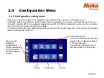
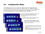
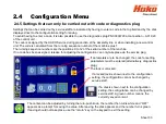
2.4.5 Settings that can only be carried out with code or diagnostics plug
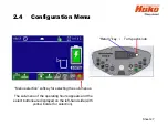
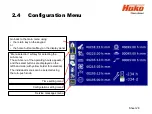
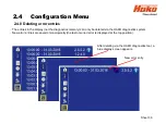
2.4 Configuration Menu
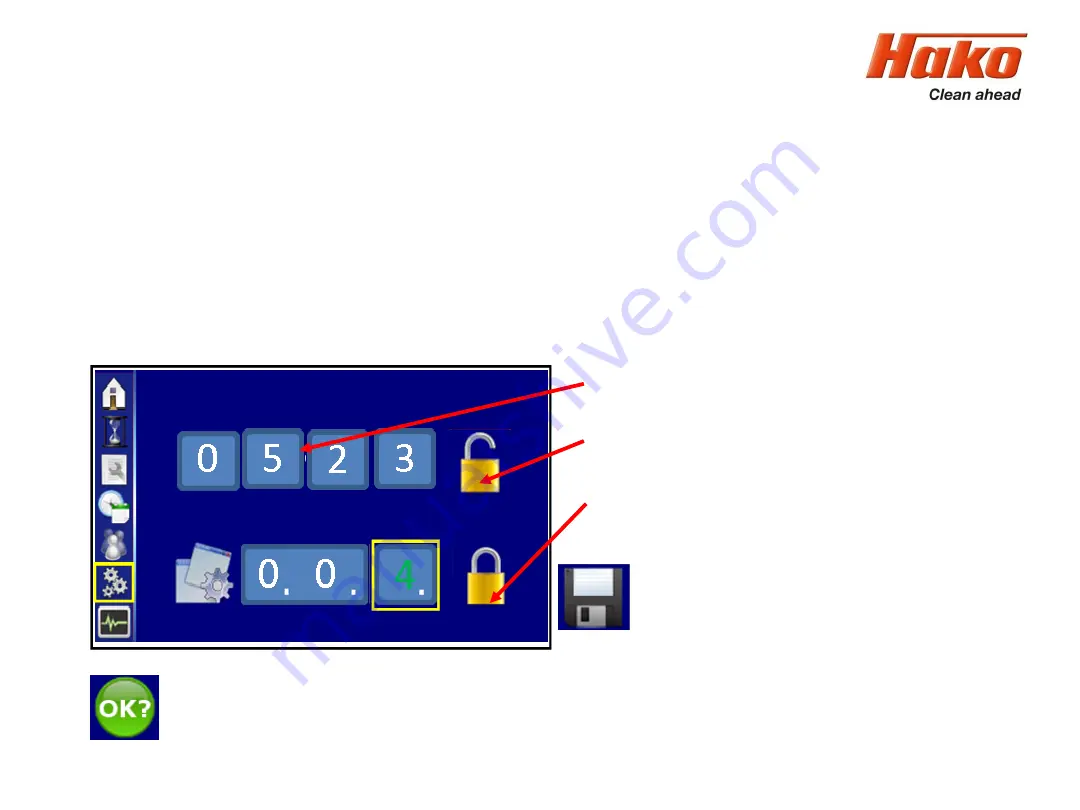
Settings that can be carried out by service staff are indicated by having to enter a code in the top field and by the disk
displayed next to the configuration setting for saving.
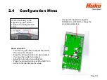
To avoid having to enter a code, it is also possible to use the diagnostics plug PN 03006790 at connection
– A01.X20
of the control unit.
The code is assigned by the HAKO Service during production at the assembly line or when installing a new control
unit. The code is calculated from the running sequence number of the machine plus 1.
The running sequence numbers are the positions 9 to 12 of the serial number of the machine.
If no code has been assigned, release for adjusting the configuration can only take place via the service plug.
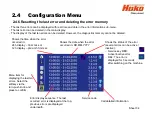
If parameters are to be changed, the code for setting
parameters must be entered (alternatively, diagnostics
plug).
The lock is unlocked.
If a locked lock is shown next to the configuration
setting, the configuration cannot be changed by
service staff.
If a disk is shown next to the configuration
setting, the configuration can be changed by
service staff. A green number means: the
currently saved content.
The content can be adjusted by turning the turn-
push knob, the number then turns white and “OK?”
appears as a prompt for saving the value. After saving, the disk appears and the number turns green.
If saving should not take place, use the “return” key on the keypad to exit the setting.
Sheet 33
Summary of Contents for Scrubmaster B175 R
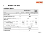
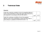
Page 37: ...3 Technical Data Sheet 37...
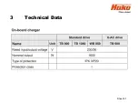
Page 38: ...3 Technical Data Sheet 38...
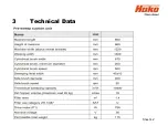
Page 39: ...3 Technical Data Sheet 39...
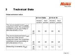
Page 40: ...3 Technical Data Sheet 40...
Page 41: ...3 Technical Data Sheet 41...
Page 42: ...3 Technical Data Sheet 42...
Page 43: ...3 Technical Data Sheet 43...
Page 44: ...3 Technical Data Sheet 44...
Page 46: ...4 1 Hako System Maintenance customer Sheet 46...
Page 47: ...4 1 Hako System Maintenance customer Sheet 47...
Page 48: ...4 2 Hako System Maintenance I Sheet 48...
Page 49: ...4 2 Hako System Maintenance I Sheet 49...
Page 50: ...4 2 Hako System Maintenance I Sheet 50...
Page 51: ...4 3 Hako System Maintenance II Sheet 51...
Page 52: ...4 4 Hako System Maintenance III S Safety Check Sheet 52...
Page 65: ...6 Machine settings 6 1 6 Charging characteristics for integrated charger Sheet 65...
Page 74: ...7 Mechanical components Figure 7 2a Figure 7 2b Sheet 74 7 1 Squeegee...
Page 76: ...7 Mechanical components Height adjustment Figure 7 4 Sheet 76 7 1 Squeegee...
Page 104: ...9 Drive 9 2 4 Steering angle sensor Figure 9 5 180 130 170 150 120 Folie 104...
Page 113: ...11 Battery charger 11 1 Operating manual Sheet 113...
Page 114: ...11 Battery charger Sheet 114 11 1 Operating manual...
Page 115: ...11 Battery charger Sheet 115 11 1 Operating manual...
Page 116: ...11 Battery charger Sheet 116 11 1 Operating manual...
Page 123: ...13 Notes Sheet 123...
Page 124: ...Sheet 124 13 Notes...