5. Cleaning Programs (FPV)
Sheet 53
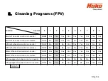
The cleaning programmes are used to control the behaviour of the water supply to the
brushes, the brush motors with regard to the position of the driving direction switch
and the speed control potentiometer (forwards, neutral, reverse) as well as the
squeegee.
A GND signal is connected to input A04:A3 of the drive control unit via the speed
control potentiometer switch in B03. This is the release signal for the drive control unit.
When driving direction forwards is selected on the control panel, this signal is
connected to input A04:A1 from A02:X109.3. When reversing is selected, the signal is
connected to input A04:A2 from A02:X109.4. If these signals are missing at A04:A1 or
A04:A2, the machine cannot be driven.
The “forwards” and “reverse” signals are transferred to the machine control unit via
CAN-bus and the cleaning units are therefore activated. The behaviour of the cleaning
functions is described in Table 5.1.
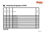
In order to select a cleaning programme, you must switch to the programming level as
described in Chapter 2.4 Configuration (sub-chapters 2.4.3 and 2.4.4). The available
cleaning programmes are listed in Table 5.2.
Summary of Contents for Scrubmaster B175 R
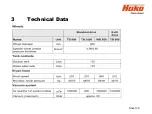
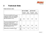
Page 37: ...3 Technical Data Sheet 37...
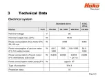
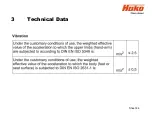
Page 38: ...3 Technical Data Sheet 38...
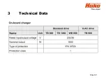
Page 39: ...3 Technical Data Sheet 39...
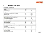
Page 40: ...3 Technical Data Sheet 40...
Page 41: ...3 Technical Data Sheet 41...
Page 42: ...3 Technical Data Sheet 42...
Page 43: ...3 Technical Data Sheet 43...
Page 44: ...3 Technical Data Sheet 44...
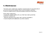
Page 46: ...4 1 Hako System Maintenance customer Sheet 46...
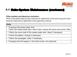
Page 47: ...4 1 Hako System Maintenance customer Sheet 47...
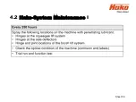
Page 48: ...4 2 Hako System Maintenance I Sheet 48...
Page 49: ...4 2 Hako System Maintenance I Sheet 49...
Page 50: ...4 2 Hako System Maintenance I Sheet 50...
Page 51: ...4 3 Hako System Maintenance II Sheet 51...
Page 52: ...4 4 Hako System Maintenance III S Safety Check Sheet 52...
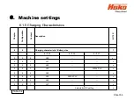
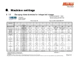
Page 65: ...6 Machine settings 6 1 6 Charging characteristics for integrated charger Sheet 65...
Page 74: ...7 Mechanical components Figure 7 2a Figure 7 2b Sheet 74 7 1 Squeegee...
Page 76: ...7 Mechanical components Height adjustment Figure 7 4 Sheet 76 7 1 Squeegee...
Page 104: ...9 Drive 9 2 4 Steering angle sensor Figure 9 5 180 130 170 150 120 Folie 104...
Page 113: ...11 Battery charger 11 1 Operating manual Sheet 113...
Page 114: ...11 Battery charger Sheet 114 11 1 Operating manual...
Page 115: ...11 Battery charger Sheet 115 11 1 Operating manual...
Page 116: ...11 Battery charger Sheet 116 11 1 Operating manual...
Page 123: ...13 Notes Sheet 123...
Page 124: ...Sheet 124 13 Notes...

