
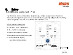
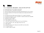
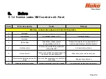
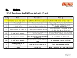
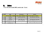
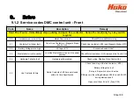
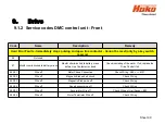

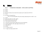
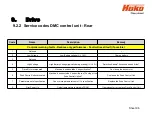
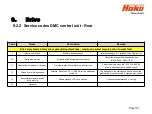

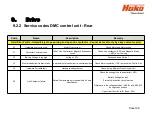
9. Drive
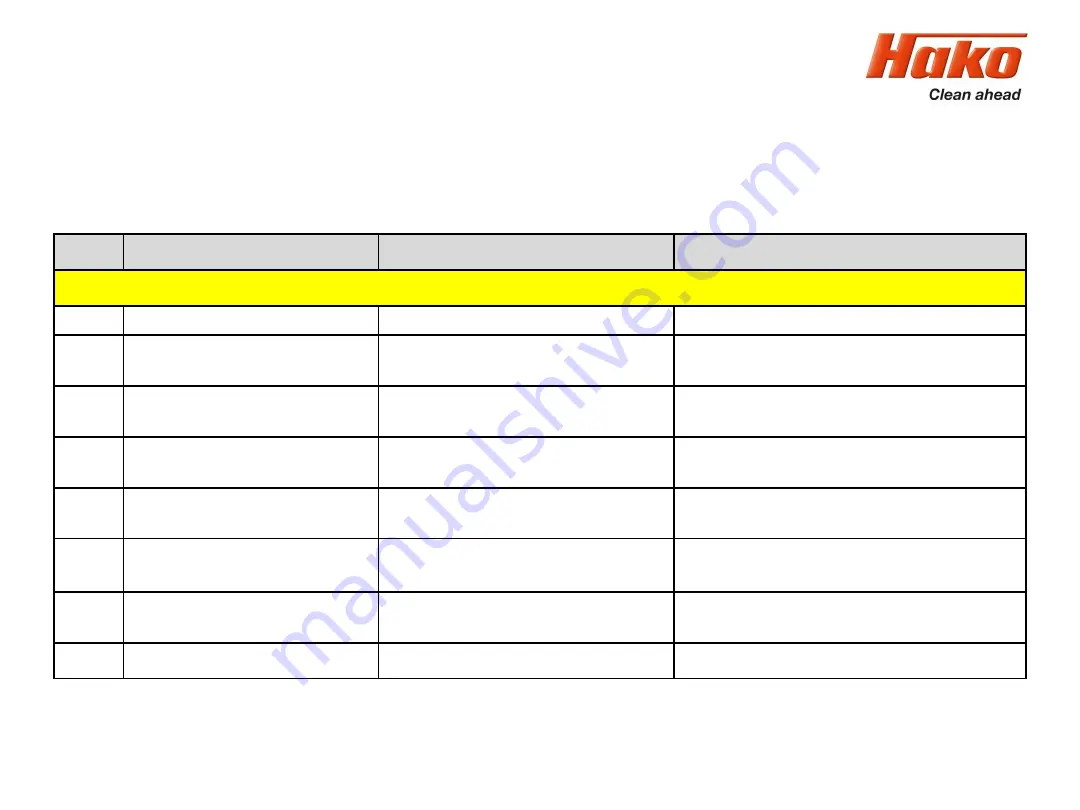
9.1.2 Service codes DMC control unit - Front
Sheet 87
Code
Name
Description
Remedy
Drive error faults -Commences gracefull neutral brake - requires a neutral recycle action to reset fault
9
Memory chip fault
Memory not accessible
Internal voltage <12V; replace Drive Control Unit
10
2 directions active
forward and Reverse direction active
Check the wiring of the direction switch
(-A02.X6 and -A04.A1/A2)
11
Seat switch not closed or timed out No release signal from Machine Control Unit
Check the wiring from -A01.X10:2 to -A04.A4
(should be connected to battery minus)
12 S01
Wrong Power Up sequence
Forward, Reverse or FS1 (-A04.A3) active
before key switch on
Pay attention to the starting sequence: key switch /
seat switch, direction switch, potentiometer switch.
12 S02
Wrong Power Up sequence
Rear Controller Anti Roll back at ramp and
active brake
Check the EM brake of teh rear axle
12 S03
Wrong Power Up sequence
Rear controller micro switch on EM brake is
active
Check deactivation of rear motor EM brake
13
Accelerator signal is active
at Power Up
Speed signal is >50% at power up
Check potentiometer and it´s wiring
14
CAN-Bus
Stop via CAN
Machine Control unit send Stop Signal via CAN-Bus
Summary of Contents for Scrubmaster B175 R
Page 37: ...3 Technical Data Sheet 37...
Page 38: ...3 Technical Data Sheet 38...
Page 39: ...3 Technical Data Sheet 39...
Page 40: ...3 Technical Data Sheet 40...
Page 41: ...3 Technical Data Sheet 41...
Page 42: ...3 Technical Data Sheet 42...
Page 43: ...3 Technical Data Sheet 43...
Page 44: ...3 Technical Data Sheet 44...
Page 46: ...4 1 Hako System Maintenance customer Sheet 46...
Page 47: ...4 1 Hako System Maintenance customer Sheet 47...
Page 48: ...4 2 Hako System Maintenance I Sheet 48...
Page 49: ...4 2 Hako System Maintenance I Sheet 49...
Page 50: ...4 2 Hako System Maintenance I Sheet 50...
Page 51: ...4 3 Hako System Maintenance II Sheet 51...
Page 52: ...4 4 Hako System Maintenance III S Safety Check Sheet 52...
Page 65: ...6 Machine settings 6 1 6 Charging characteristics for integrated charger Sheet 65...
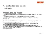
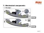
Page 74: ...7 Mechanical components Figure 7 2a Figure 7 2b Sheet 74 7 1 Squeegee...
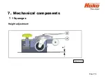
Page 76: ...7 Mechanical components Height adjustment Figure 7 4 Sheet 76 7 1 Squeegee...
Page 104: ...9 Drive 9 2 4 Steering angle sensor Figure 9 5 180 130 170 150 120 Folie 104...
Page 113: ...11 Battery charger 11 1 Operating manual Sheet 113...
Page 114: ...11 Battery charger Sheet 114 11 1 Operating manual...
Page 115: ...11 Battery charger Sheet 115 11 1 Operating manual...
Page 116: ...11 Battery charger Sheet 116 11 1 Operating manual...
Page 123: ...13 Notes Sheet 123...
Page 124: ...Sheet 124 13 Notes...


