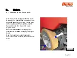
background image


9.   Drive 

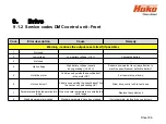
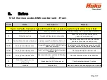
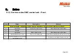
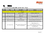
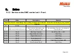
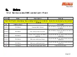
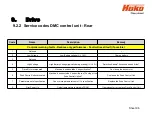
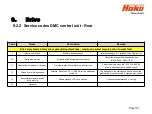
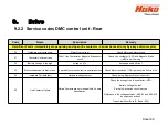
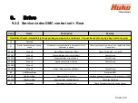
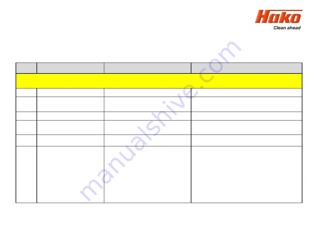
9.1.2  Service codes DMC control unit - Front 

Sheet 89


Code 

Name 

Description 

Remedy 

Hard Error Faults - Immediately stops pulsing and open line contactor - Cannot be reset (only by a key switch 

recycle) 

20 

Hardware over current trip 

Motor Over current 

Check Motor and Motor wiring 

21 

Contactor Coil driver fault 

Coil of Line Contactor or Magnetic Brake 

short circuit 

Check Line contactor (-K02) and Magnetic Brake(-M01) 

22 

Battery Voltage is too high 

Voltage > 67V 

Excessive downhill ride? 

23 

Mosfet short circuit in neutral 

Low side Mosfet short ciionrcuit in neutral 

position 

Check Motor Insulation, if OK, replace drive Control Unit 

24 

Hardware Fail safe fault 

Hardware safty problem 

Check wiring. Replace Drive Control Unit. 

25 

Line Contactor failure 

Relais Contacts of -K02 are not closed 

within it´s time Specification 

Check the wiring of the line contactor (-K02) 

Battery Voltage too low? 

E-stop in Key switch circuit is active 

Difference in the voltage between A04.B+ and A04.A10 

during start up check 

Open circuit from B+ to B- (Fuse -F03) 

Summary of Contents for Scrubmaster B175 R

Page 1: ...Booklet Hako GmbH Technisches Produktmanagement D 23840 Bad Oldesloe Updated 03 2019 Rev 1 03 Vertraulich nur f r den internen Gebrauch Confidential For internal use only Schulung Training Fehlersuch...

Page 2: ...off suction waste water tank full 15 2 2 2 Solution tank display 16 2 2 3 Machine home position 17 2 2 4 Seat contact switch 3 6 6 4 18 2 3 Diagnostics and communications 20 2 3 1 Prerequisites 20 2...

Page 3: ...tings that can only be carried out with code 33 2 4 6 Resetting the last error and deleting the error memory 34 2 4 7 Deleting the last error on the display panel 35 2 4 8 Deleting error entries 36 3...

Page 4: ...stic curves 64 6 1 6 Charging data table of the integrated charger 65 6 1 7 All wheel drive variant X AC 66 6 1 8 SD storage medium in control panel 67 6 2 Customer specific settings PPV 68 7 Mechanic...

Page 5: ...ive control unit front 84 9 1 2 Service codes drive control unit front 86 9 1 3 Brake manual release of the brake front 92 9 1 4 Brake testing the brake function 93 9 2 DMC drive control unit rear 94...

Page 6: ...rvice messages 106 10 1 Meaning of different switch on displays 111 10 2 Service alarm clock 3 3 1 1 112 11 Battery charger 113 11 1 Operating manual 113 11 2 Programming the charger 117 12 Options 11...

Page 7: ...hen it has been de energised disconnect the battery plug except for current and voltage measurements After repairing electrical drives measure the starting and operating currents to detect possibly st...

Page 8: ...ses are displayed and machine settings can be made If a fault occurs the wrench in the display lights up and the machine beeps The current service code four digit alphanumerical code in the service in...

Page 9: ...on machines and configuration machines Edition machines are machines that have a clearly defined scope of equipment In this context only a limited scope of additional equipment features is available A...

Page 10: ...manufactured order specifically according to customer wishes from a pool of available equipment features Additional options chemical dosing working light warning signal etc are installed in the facto...

Page 11: ...r without restrictions e g cleaning programmes in Chapter 3 and several settings in Chapter 2 This is always possible if a diskette is displayed next to the value Chapter Configuration Content However...

Page 12: ...This is required to make the control panel work A micro SD card with the required image file can be written to using the Hako diagnostics If the micro SD card is missing or the image file on the card...

Page 13: ...an indeterminate state since no data has been transferred from the machine control unit to the control panel Therefore the machine software must be flashed onto the central control unit after mechani...

Page 14: ...messages of the drive control unit on the display of the machine these are displayed as detailed flash codes on the drive control using flashing LEDs see Chapter 9 It is possible to toggle back and fo...

Page 15: ...he signal waste water tank full to protect the suction turbine Switching off by the operator The squeegee is raised The suction motor switches off with a delay 15 seconds Switching off because the tan...

Page 16: ...a the immersion tube and the hoses which is converted into an electrical signal by the electronics of the pressure sensor This signal is evaluated by the machine control unit and shown on the display...

Page 17: ...ed The lifting elements will lift unless they have been switched off via the micro switch for the upper end position integrated in the lifting element squeegee or the upper end position is detected by...

Page 18: ...ch is not actuated for 6 hours while the key switch is switched on the machine is locked in all functions driving and cleaning The same applies if both contacts of the seat contact switch have the sam...

Page 19: ...while the machine is on A seat contact switch that has been detected as open by the machine no operator on the seat is indicated on the control panel display via the operator in the top line of the MF...

Page 20: ...crubmaster B175 R after a replacement Current Hako diagnostic software via the Hako WebX download portal Service PC e g Panasonic CF19 CF20 Interface PN 03502430 preferred variant or alternatively als...

Page 21: ...e or as a folder from the Hako WebX download area Information on accessing the download server can be requested from Maike Christiansen e mail mchristiansen hako com To install the software on a servi...

Page 22: ...stablish a connection between the machine and the diagnostic computer using the diagnostic cable PN 03502750 and the interface PN 03502430 or 03501750 Connect the OBD connector blue contact protection...

Page 23: ...use the D Sub 9 connection with the designation RS232 With CANUSB interface PN 03501750 alternative connecting option Connect the D Sub 9 connection of the diagnostic cable marked CAN1 red marking to...

Page 24: ...iagnostic PC 2 3 Diagnostics and communication CAN Fox Interface PN 03502430 USB connector to Service PC D Sub9 connector CAN D Sub9 Connector RS232 D Sub9 Socket CAN1 RED D Sub9 Socket CAN2 BLACK OBD...

Page 25: ...k the Scrubmaster B175 R button The application independently searches for a new blank control unit Follow the instructions of the programme Do not turn off the machine or disconnect the connection be...

Page 26: ...rview Select the sub menus In the main display screen use the turn push knob to select the red button with the green arrow and actuate it by pressing the turn push knob The display screen jumps into t...

Page 27: ...for selecting the sub menus The sub menu of the operating hours appears and the select buttons are displayed on the left hand side with yellow border for selection Return key Turn push knob 2 4 Confi...

Page 28: ...el Menu selection softkey for selecting the sub menus The sub menu of the operating hours appears and the select buttons are displayed on the left hand side with yellow border for selection The indivi...

Page 29: ...ter can be adjusted Press again to save Turn further to the next value to be adjusted Values are saved automatically when exiting the menu item turning the turn push knob on the time setting menu item...

Page 30: ...evice and non adjustable values can only be changed via a software update Turn the turn push knob to the adjustable parameter and press If the border turns green the content can be adjusted Save the v...

Page 31: ...ob to access the field of the value to be changed Press the turn push knob to be able to adjust the value the border turns green Adjust by turning the turn push knob Press the turn push knob to exit t...

Page 32: ...or wants to adjust parameters only released parameters can be adjusted The lock is locked If a locked lock is shown next to the configuration setting the configuration cannot be changed by the operato...

Page 33: ...sitions 9 to 12 of the serial number of the machine If no code has been assigned release for adjusting the configuration can only take place via the service plug If parameters are to be changed the co...

Page 34: ...urred in 24 h display hh mm ss or 12 h display pm am hh mm ss Shows the date when the error occurred in DD MM YYYY Menu item for displaying the last ten errors Select the softkey via the turn push kno...

Page 35: ...DEL between time date and the error message of the last occurred error DEL is only visible if the error has been reset i e the service key has extinguished Press and hold the turn push knob for 3 sec...

Page 36: ...not the diagnostics memory can only be deleted via the HAKO diagnostics system New error entries are saved chronologically the last occurred error is displayed at the top position After deleting via t...

Page 37: ...3 Technical Data Sheet 37...

Page 38: ...3 Technical Data Sheet 38...

Page 39: ...3 Technical Data Sheet 39...

Page 40: ...3 Technical Data Sheet 40...

Page 41: ...3 Technical Data Sheet 41...

Page 42: ...3 Technical Data Sheet 42...

Page 43: ...3 Technical Data Sheet 43...

Page 44: ...3 Technical Data Sheet 44...

Page 45: ...e maintenance activities Parts to be replaced for the individual maintenance tasks are determined Hako system maintenance Assures the reliable readiness for use of the Hako cleaning machines preventiv...

Page 46: ...4 1 Hako System Maintenance customer Sheet 46...

Page 47: ...4 1 Hako System Maintenance customer Sheet 47...

Page 48: ...4 2 Hako System Maintenance I Sheet 48...

Page 49: ...4 2 Hako System Maintenance I Sheet 49...

Page 50: ...4 2 Hako System Maintenance I Sheet 50...

Page 51: ...4 3 Hako System Maintenance II Sheet 51...

Page 52: ...4 4 Hako System Maintenance III S Safety Check Sheet 52...

Page 53: ...ction forwards is selected on the control panel this signal is connected to input A04 A1 from A02 X109 3 When reversing is selected the signal is connected to input A04 A2 from A02 X109 4 If these sig...

Page 54: ...ve control is in neutral SOW No No No Yes Yes Yes Yes No No Lift brush when drive control is in reverse SOW No No No No No Yes No No No Water off when drive control is in neutral SOW Yes Yes Yes Yes Y...

Page 55: ...cription B175R 3 0 Adjusted FPV 0 3 0 1 Refer to FPV table x 3 0 2 Refer to FPV table d 3 0 3 Refer to FPV table x 3 0 4 Refer to FPV table x 3 0 5 Refer to FPV table x 3 0 6 Refer to FPV table x 3 0...

Page 56: ...B175 R offers different equipment options and working widths These can be set and adapted in the configuration menu To check and change the setting access the configuration menu as described in Chapte...

Page 57: ...08 cm and a cylindrical brush unit with a working width of 85 cm This setting is necessary for correct functioning of the overrange limits and water quantities To check and change the setting of the c...

Page 58: ...ttings Table 6 1 Sheet 58 Chapter Configuration Content Description B175R 0 2 Brush decks 1 0 2 4 Plate brush deck 900mm x 0 2 7 Cylindrical brush deck 850mm x 0 2 A Plate brush deck 1080mm x 6 1 1 Cl...

Page 59: ...ings are carried out in the menu items 0 3 X 0 4 X and 0 5 X If the setting for a machine without charger 0 4 0 with charger and without communication 0 4 1 or for a charger with communication and fre...

Page 60: ...ies PzS are sealed low maintenance batteries containing liquid electrolyte Regular checking of the electrolyte as well as topping up with distilled water are required here AGM batteries have glass mat...

Page 61: ...uration Content Description B175R 0 3 LDS Adjustment Battery Type only for 0 4 0 0 4 1 and 0 4 2 1 0 3 0 Crown w o Offset x 0 3 1 Crown x 0 3 2 GIS Foreign x 0 3 3 GiS x 0 3 4 PzS or PzB Foreign x 0 3...

Page 62: ...aracteristic curve selection is selected the correct characteristic curve must be determined using the charger documents and then set correctly under 0 5 X The column under 0 4 2 in Table 6 4 then app...

Page 63: ...ttery charger and Battery types 1 0 4 0 w o battery charger x 0 4 1 battery charger w o communication x 0 4 2 Battery charger with communication manual charging characteristics selection x 0 4 6 Batte...

Page 64: ...64 Chapter Configuration Content Description B175R 0 5 Charging characteristic Battery size 1 for 0 4 2 for 0 4 6 for 0 4 7 0 5 0 LK0 x 0 5 1 LK1 x 0 5 2 LK2 x 0 5 3 LK3 320Ah PzS x 0 5 4 LK4 x 0 5 5...

Page 65: ...6 Machine settings 6 1 6 Charging characteristics for integrated charger Sheet 65...

Page 66: ...XC Sheet 66 Table 6 6 Chapter Configuration Content Description B175R 0 6 All wheel drive installed 0 6 0 only Front wheel drive d 0 6 1 Front and Rear wheel drive x The all wheel drive variant must...

Page 67: ...dditional memory at the display 0 7 0 not available x 0 7 1 available d This parameter must not be adjusted Can currently lead to a complete failure of the machine A missing SD card in the dash board...

Page 68: ...It can e g be set whether the last error that occurred in the machine is shown when turning on the machine or not Check and change the setting as described in Chapter 2 4 Configuration The possible s...

Page 69: ...witching on machine 2 0 0 Deactivate x 2 0 1 Activate d 2 1 Water level when switching on scrubbing 2 1 0 Last stage set d 2 1 1 Preset level 4 x 2 3 Water level when switching on TOOL menu option onl...

Page 70: ...On drive pedal neutral 2 5 0 Deactivate d 2 5 1 Activate x 2 7 Silence Mode Setting 2 7 0 Is not saved x 2 7 1 Is saved d 2 8 Acoustic Alarm Tone Interval menu option only appears when the Acoustic A...

Page 71: ...setting of adjusting bushing see figure 7 1 dimensions 9 and 8 mm 2 Screw on the squeegee which is intended for the machine and align via the adjusting bushing so that the sealing strips are vertical...

Page 72: ...7 Mechanical components Figure 7 1 Squeegee connection 8 1 mm 9 1 mm Adjusting bushing Fork head Base plate Sheet 72 7 1 Squeegee...

Page 73: ...en the lock nuts figure 7 2a A and adjust the squeegee by turning the adjusting bushing figure 7 2a B so that the ends of the sealing strips are just about touching the ground Turning the adjusting bu...

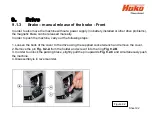
Page 74: ...7 Mechanical components Figure 7 2a Figure 7 2b Sheet 74 7 1 Squeegee...

Page 75: ...ust the distance between the supporting rollers and the lower edge of the sealing strip 1 Place the machine on a level surface 2 Lower squeegee The sealing strips must now be resting vertically onto t...

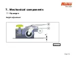
Page 76: ...7 Mechanical components Height adjustment Figure 7 4 Sheet 76 7 1 Squeegee...

Page 77: ...eads in two working widths 90 cm and 108 cm are used with the Scrubmaster B175 R Both brushes are driven by a separate motor The left and right brushes on the plate brush unit both rotate clockwise Th...

Page 78: ...is used as the cylindrical brush unit for the Scrubmaster B175 R The cylindrical brush unit can also be extended with a side broom unit Use the guide rail to adjust the dirt hopper ensuring the brush...

Page 79: ...he brush head features integrated position detection The position detection is supplied with 24V via the machine control unit A01 X13 1 and A01 X13 7 The reference signal for the brush head position c...

Page 80: ...d here depend on numerous factors it is therefore not possible to specify exact values Decisive is that the voltage values differ considerably from the lowest to the highest stage Checking of the actu...

Page 81: ...in the 5 water stages for the three brush units are listed in the following table Water quantities l per min Plate brush 900 mm Plate brush 1080 mm Roller brush 850 mm Stage 1 1 6 1 6 1 3 Stage 2 3 3...

Page 82: ...ds up behind the pump Without protection from the electronics the pump will now continue to pump against this pressure and may be damaged The electronics detects that the pump cannot convey freely and...

Page 83: ...in The speed control potentiometer must also be in neutral when the seat contact switch is closed or to be more precise it must be detected as being in neutral by the drive control unit If the drive c...

Page 84: ...documents changes to the preset values and parameters is generally not permitted Currently only the diagnostics with flash codes for the LED indicator is used 9 1 1 Connection description M1 M2 M3 mot...

Page 85: ...le wheel drive at battery minus via bridge on X11 not used for 4 wheel drive A7 foot brake input from switch S10 if B is connected the machine is slowed down until standstill A8 supply speed control B...

Page 86: ...pay attention to machine specifications defective battery 5 Hot drive motor Vehicle used outside the specification Is the motor OK Let the motor cool down 6 Hot control unit Vehicle used outside the s...

Page 87: ...he wiring from A01 X10 2 to A04 A4 should be connected to battery minus 12 S01 Wrong Power Up sequence Forward Reverse or FS1 A04 A3 active before key switch on Pay attention to the starting sequence...

Page 88: ...Low voltage internal 12V supply too low Check charging level of the battery 16 Not used 17 Low voltage Battery voltage too low Check charging level of the battery 18 High Side Mosfet short circuit Sho...

Page 89: ...1 22 Battery Voltage is too high Voltage 67V Excessive downhill ride 23 Mosfet short circuit in neutral Low side Mosfet short ciionrcuit in neutral position Check Motor Insulation if OK replace drive...

Page 90: ...rcuited to battery minus before Line Contactor is closed Check insulating of the motor If ok replace the Drive Control Unit 28 S01 Wire off Motor Phase Connection Check Wiring A04 M01 28 S02 Wire off...

Page 91: ...29 S02 CAN Fehler Front controller security bit error Check CAN Bus connection between front and rear controller 29 S03 CAN Fehler Timeout Front Controller and Machine controller Check CAN Bus Drive c...

Page 92: ...eleased manually In order to push the machine carry out the following steps 1 Loosen the bolts of the cover to the drive using the supplied socket wrench and remove the cover 2 Remove the pin Fig 9 2...

Page 93: ...chine on a level road within 0 19 m per km h At a maximum speed of 8 km h this means that the maximum braking distance must not exceed 1 52 m Check this after carrying out work at the brake system and...

Page 94: ...control unit Rear A05 is only via CAN Bus The two drive control unit have different parameter sets Therefore the never have to be exchanged 9 2 1 Connection description M1 M2 M3 motor connections B B...

Page 95: ...unit is deactivated if the brake is manually released signal from A05 A11 36V A7 not used A8 supply steering angle sensor R20 negative A9 setpoint from steering angle sensor R20 A10 control voltage fr...

Page 96: ...raking U 60V Defective Battery Excessive downhill ride 5 Drive Motor overheated Machine is used outside it s specification Cool down the drive motor 6 Drive Control Unit overheated Machine is used out...

Page 97: ...ive Check the wiring of the direction switch A02 X6 and A04 A1 A2 11 Seat switch not closed or timed out No release signal from Machine Control Unit Check the wiring from A01 X10 2 to A05 A4 should be...

Page 98: ...ault 15 Low voltage internal 12V supply too low Check charging level of the battery 16 Safety line error Drive control rear is ok Error from drive control front A04 A14 A05 C3 17 Low voltage Battery v...

Page 99: ...it s wiring 22 Battery Voltage is too high Voltage 67V Excessive downhill ride 23 Mosfet short circuit to Batt minus Low side Mosfet short circuit in neutral position Check Motor Insulation if OK rep...

Page 100: ...S01 Wire off Motor Phase Connection Rear Check Wiring A05 M02 28 S02 Wire off Magnetic Brake short circuit Rear Check Wiring 28 S03 Wire off Magnetic Brake wire off Rear Check Wiring 28 S04 Wire off...

Page 101: ...at the rear axle has to be unlocked Lift the lever on the right side of the machine next to the rear wheel till it snaps into place Figure 9 4 A When the rear brake is disengaged a indication in the M...

Page 102: ...steering angle of the front wheel drive For this reason a rotary sensor is installed at the front wheel drive After the sensor is replaced the sensor may need accurate adjustment The procedure is des...

Page 103: ...a long screw Fit Screw pos 130 and washer pos 180 with threadlocker e g Loctite 243 Tightening torque 9 3 Nm Install the feather key pos 200 and grease the upper end of the shaft as a corrosion prote...

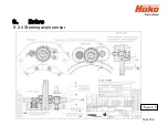
Page 104: ...9 Drive 9 2 4 Steering angle sensor Figure 9 5 180 130 170 150 120 Folie 104...

Page 105: ...e sensor Flange bushing Shaft Screw M6x20 DIN 4762 Spur gear Screw M6x16 DIN 7984 Washer 10 5 DIN 125 Washer 6 4 DIN 9021 Feather key A 3x3x8 DIN 6885 Lock Washer 6 Parts List Pc Pc Pc Pc Pc Pc Pc Pc...

Page 106: ...6 1 Brush motor 1 left overload Short circuit in the brushmotor M03 or in it s wiring Brush motor overload 1 2 6 3 Lifting element brush deck Overload of the brush deck lifting element or short circui...

Page 107: ...broom motors and wiring thermo switches option side broom 2 3 6 1 Blocking protection side broom motor left and right Short circuit in the side broom motors or in it s wiring option side broom 2 3 6 4...

Page 108: ...zer magnetic valve Etc 3 4 1 1 Malfunction drive control unit pre selection of driving direction implausibly or interrupted wiring accelerator Check wiring of the accelerator B03 and direction switch...

Page 109: ...ve control unit front CAN Bus error between machine control unit and drive control unit A01 A04 4 2 3 1 Communication problem drive control unit rear CAN Bus error between machine control unit and dri...

Page 110: ...battey charger battery related problems See battery charger manual Malfunction 5 8 7 3 Battery charger Wrong charging characteristic adjusted See blinking code at the drive control unit 5 8 7 4 Chargi...

Page 111: ...ith time and Servicecode 2 Display when the operating system at the machine control system is missing isn t started or the CAN connection between machine control unit and dash board is interrrupted pe...

Page 112: ...10 2 Service alarm clock 3 3 1 1 Sheet 112 The service alarm clock is set via the Hako diagnostic system...

Page 113: ...11 Battery charger 11 1 Operating manual Sheet 113...

Page 114: ...11 Battery charger Sheet 114 11 1 Operating manual...

Page 115: ...11 Battery charger Sheet 115 11 1 Operating manual...

Page 116: ...11 Battery charger Sheet 116 11 1 Operating manual...

Page 117: ...11 Battery charger The integrated charger is adjusted and parametrised exclusively via the machine control unit See Chapter 6 1 4 and 6 1 5 Sheet 117 11 1 Programming the charger...

Page 118: ...the options are available only with the latest software revision Some options may require additional hardware which cannot be fitted to old machines Silence Kit suction turbine rotating speed reductio...

Page 119: ...The mechanical installation of the field options if necessary is described in the supplied instructions for these field options The options acoustic and optical warning signal and Blue Spotcan not be...

Page 120: ...n B175R 1 0 Silence Kit 1 0 0 not available x 1 0 1 available d 1 1 Warning Signal Optical and acoustical 1 1 0 not available d 1 1 1 available x 1 2 Chemical Dosing Agent 1 2 0 not available d 1 2 1...

Page 121: ...Description B175R 1 4 Pre Sweep Unit 1 4 0 not available d 1 4 1 available x 1 6 Working Headlight 1 6 0 not available d 1 6 1 available x 1 7 Fleetrecorder 1 7 0 not available d 1 7 1 available x 1 8...

Page 122: ...ond Suction Motor 1 9 0 not available d 1 9 1 available x 1 A Warning Beacon on Pole 1 A 0 not available d 1 A 1 available x 1 B TOOL Spinkle Nozzle for cleaning of the recovery tank 1 B 0 not availab...

Page 123: ...13 Notes Sheet 123...

Page 124: ...Sheet 124 13 Notes...

Reviews: