


Slide 91
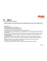
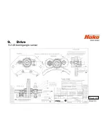
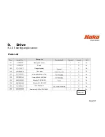
9.
Drive
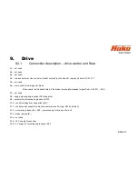
9.2.1
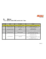
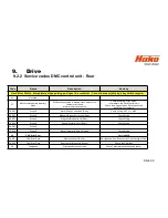
Connection description – drive control unit Rear
A1 – not used
A2 – not used
A3 – not used
A4 – release from machine control unit (seat contact) (active when B- is present) from A01/X13.11
A5 – not used
A6 – micro switch from magnetic brake;
Drive control unit is deactivated, if the brake is manually released (signal from –A05.A11 – 36V)
A7 – not used
A8 – supply steering angle sensor R20 (negative)
A9 – setpoint from steering angle sensor R20
A10 – control voltage from key switch (36V)
A11 – control power supply for small consumers (max. 3A) (e.g. K03 and brake)
A12 – main relay release (B-) –K03 – power supply for drive control unit
A13 – brake release (B-)
A14 – not used
A15 – 12 V supply for encoder
A16 – 5 V supply for steering angle sensor R20
Summary of Contents for Scrubmaster B260 R
Page 64: ...Slide 64 Figure 7 2a Figure 7 2b 7 Mechanical components 7 1 Squeegee...
Page 66: ...Slide 66 Figure 7 4 7 Mechanical components Height adjustment 7 1 Squeegee...
Page 100: ...180 130 170 150 120 Figure 9 5 Slide 100 9 Drive 9 2 4 Steering angle sensor...
Page 121: ...Slide 121 14 Notes...


