25
Operation
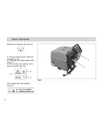
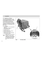
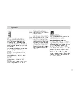
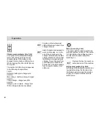
Charge mode indicator (Fig. 9/2)
Four green LEDs indicate the charge
mode with reference to the current
charging stage. If the battery is dis-
charged, the two bottom LEDs light up.
While charging, the other LEDs light up
one by one.
The number of LEDs lit up corresponds
to the following charge status:
1 LED:
Soft start, battery pre-charge cycle
2 LEDs
Main charge cycle - battery is being
charged
3 LEDs
Trickle charge - charge level 80%
4 LEDs
Charge cycle complete - charge level
100%. Charge retention is enabled
Flashing of the bottommost
LED is indicative of a fault. See
charger manual.
Hako chargers are designed to
work continuously, i.e., at the
end of the charge cycle, the
charger automatically enables
charge retention to ensure that
the battery is always perfectly
charged. To get the most from
your battery and optimize its
service life, it is best to always
fully charge the battery (four
LEDs on).
Main switch (Fig. 9/3)
The main switch is used to switch the
electrical system on and off.
Bail system switch (Fig. 9/4)
Letting go of the bail system switch dur-
ing operation stops the brush head
drive and the solution supply. The suc-
tion turbine remains switched on.
Pulling up the bail system switch en-
ables the brush head drive's power flow
effect to support the machine drive.
Brush ejection button (Fig. 9/5)
Press the brush ejection button to eject
the brush for maintenance purposes,
see paragraph 0.1.1

