background image

40

05-7150-00.fm

Maintenance and servicing

5.5

Cleaning/replacing the cleaning tools

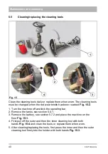
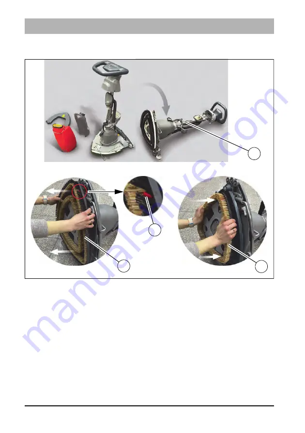
Clean the cleaning tools daily or replace them when worn. The cleaning tools 
must be changed when the red wear bristle has been reached 

Fig. 15-2

.

1. Turn the machine off and lock the operating bar.
2. Remove the tanks, see section 5.4.1.
3. Remove the battery, see section 5.7.2


and place the machine on the 

floor 

Fig. 15-1

.

4. First pull off the outer and then the inner cleaning tool with both 

hands 

Fig. 15-4 

and clean the tools, or replace them when worn.

5. After cleaning/replacing the tools, first press the inner and then the outer 

cleaning tool firmly into the holder with both hands 

Fig. 15-3

.

Fig. 15

2

4

3

1

Summary of Contents for Scrubmaster B5

Page 1: ...Scrubmaster B5 7150 Operating manual Part number 88 10 3353 4766 00 Valid as from 05 2023...

Page 2: ...mation for operation maintenance and servicing We have pro vided the places in this operating manual concerning your safety with a dan ger pictogram Your authorised Hako dealer is available at all tim...

Page 3: ...ion distributed by us to the usual health and safety requirements of the EC Directives see Declaration of Conformity This declaration loses its validity in the event of a modification to the machine n...

Page 4: ...rmed by the transport company and send in the damage re port together with the consignment note to us Machine data Your machine is described clearly by the following data Please always quote these dat...

Page 5: ...2 Controls and display elements 18 2 2 1 Control panel 18 2 2 2 Controls at the machine 21 2 3 General principle of operation 22 2 3 1 Driving with the Delta Cleaning system 22 2 3 2 Cleaning head 23...

Page 6: ...resh water filter 39 5 4 4 Cleaning the waste water suction hose 39 5 5 Cleaning replacing the cleaning tools 40 5 6 Squeegee 41 5 6 1 Cleaning the squeegee 41 5 6 2 Replacing the sealing strips 42 5...

Page 7: ...on of a possible danger with average risk in which death or severe physical injury can occur if it is not avoided Caution Indication of a danger with low risk in which light to medium severe physical...

Page 8: ...important information for safe operation Renew labels that are no longer legible or present With Hako AntiBac machine variants the plastic inner surface of the solution and waste water tanks contains...

Page 9: ...hibited health hazard The machine must not be used in potentially explosive atmospheres Warning The machine should only be used on level surfaces with a maximum slope of 2 Manipulating the switches an...

Page 10: ...mechanical watches and hearing aids Keep objects that can be damaged by strong magnetic fields away from the magnet Electrical system If the electrical system is faulty always turn off the machine an...

Page 11: ...are clean and dry to avoid creeping currents Protect the batteries in particular against conductive contamination e g metal dust Risk of short circuits and spark formation Do not touch the battery ter...

Page 12: ...sed batteries with the recycling symbol contain reusable commodities In accordance with the symbol showing the crossed out garbage bin these batteries must not be disposed of in the domestic waste Ret...

Page 13: ...uctions 1 7 Labels on the machine The following safety and instruction labels are affixed to the machine in a clearly visible and legible manner Renew missing or illegible labels promptly A B C D Fig...

Page 14: ...e with a high pressure cleaner Fig 1 D2 Maximum permissible slope 2 when cleaning Fig 1 D3 The label is located on the electronics cover Label QR code The label Fig 1 E is located on the container hol...

Page 15: ...02 7150 00 fm 15 Use 2 Use 2 1 Overviews 2 1 1 Front and rear view Item Designation 1 Operating handle 2 Bar Fig 2 1 2 3 4 7 8 9 10 7 11 12 13 6 14 15...

Page 16: ...le 5 Handle loop 6 Battery 7 Cleaning tools 8 Rotary lock of operating bar 9 Locking bolt of tank locking device 10 Solution tank 11 Squeegee 12 Stand for park position 13 Suction turbine hose 14 Wast...

Page 17: ...eaning tools 3 Button ON OFF 4 Button suction turbine 5 Button ECO mode 6 Symbol drive of the cleaning tools 7 Symbol suction turbine 8 Indicator operating hours meter service code 9 Symbol ECO mode 1...

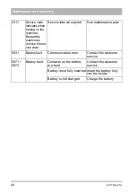
Page 18: ...hine is not operated immediately it goes into Machine lock mode after approx 10 seconds The Lock symbol appears on the display panel Briefly press the ON OFF button again to deactivate the machine loc...

Page 19: ...osing button Fig 3 1 The fresh water quantity can be set or switched off in three levels with this button Push the button to increase the water quantity by one level After reaching level 3 push the bu...

Page 20: ...isible Battery is 100 charged Four green bars visible Battery is approx 80 charged Three green bars visible Battery is approx 60 charged Two green bars visible Battery is approx 40 charged One green b...

Page 21: ...g tools and the water supply will start Locking bolt of tank cap Fig 4 2 By pulling the locking bolt and simultaneously raising the tank cap Fig 4 3 the waste water tank and the solution tank can be e...

Page 22: ...the intensive movements of the cleaning tools influenced by ECO mode or no ECO mode the machine guided by the operator glides over the floor The operator determines the driving speed and guides the m...

Page 23: ...tion tank The solution tank Fig 6 3 has a capacity of 5 litres and is filled via the filling opening in the solution tank Fig 6 4 at a sink 2 3 4 Squeegee The squeegee Fig 6 5 withdraws the waste wate...

Page 24: ...parts remove them if necessary 3 Check the battery charge and recharge it as required see chapter Maintenance 4 Fill the solution tank and add detergent according to the manufacturer s specifications...

Page 25: ...ning and care agents specifically developed for the machine These products meet the requirements of the German Detergent and Cleaning Agent Act WRMG Observe correct dosing of the detergent Correct dos...

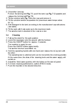
Page 26: ...order 3 4 Cleaning 1 Fold up the stand for the park position 2 Lower the squeegee onto the ground with the footrest 3 Press the ON OFF button for approx 3 seconds The machine is ready for use Press t...

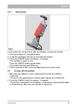
Page 27: ...e ON OFF button again briefly The suction function is switched on 4 Tilt the machine a little to the rear Fig 8 and suck up the water 3 5 Turning off the machine 1 Move the operating bar to the vertic...

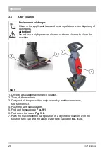
Page 28: ...cap upwards 5 Fold up the squeegee Fig 9 1 6 Fold down the stand Fig 9 2 7 Park the machine in the park position in a dry indoor location with the solution tank cap and the waste water tank cap open...

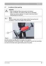
Page 29: ...and firmly secured with tension belts against tilting and rolling away Attention Risk of skidding Take extra care on wet ramps Risk of leakage The suction turbine may be damaged Empty the solution ta...

Page 30: ...y m h 900 Weights Weight empty with Li Ion battery kg 22 Total weight ready for use with Li Ion battery kg 27 Tank contents Solution tank Litre 5 Waste water tank Litre 5 Cleaning tools Speed of clean...

Page 31: ...pA at the ear of the driver measured under the customary conditions of use according to DIN EN 60335 2 72 is dB A 69 68 Measuring uncertainty KpA dB A 2 2 Under the customary conditions of use the wei...

Page 32: ...e assures the reliable readiness for use of the Hako cleaning machines preventive maintenance minimises operating costs repair costs costs for maintenance assures long life and readiness for use of th...

Page 33: ...erating hours Hako system maintenance II 500 operating hours Workshop stamp performed on at _______________ operating hours Hako system maintenance III 750 operating hours Workshop stamp performed on...

Page 34: ...the cleaning tools Clean the squeegee Charge the battery Weekly Clean the fresh water filter Check the brushes pads for wear replace if necessary Clean the waste water suction hose Check the suction...

Page 35: ...g rollers on the squeegee for ease of movement and wear replace if necessary Attention Do not loosen sealed screw connections of the supporting rollers on the squeegee holder Check the rollers and the...

Page 36: ...ce I Check the suction turbine for vacuum replace if necessary Check the condition and proper functioning of the drivers replace if necessary Check the belt strap and the spring for damage replace if...

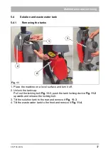
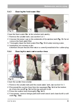
Page 37: ...machine on a level surface and turn it off 2 Unlock the tank cap Pull out the locking bolt Fig 11 1 push the tank locking device Fig 11 2 upwards and release the locking bolt 3 Tilt the solution tank...

Page 38: ...e floor Fig 12 1 and rinse them thoroughly with fresh water Fig 12 2 4 Also clean the sieve insert thoroughly Fig 12 3 5 Reinsert the tanks after cleaning and allow them to dry with the tank cap up an...

Page 39: ...ter 4 Installation is in reverse order Attention Ensure that the filter sieve is correctly installed in the rubber plug 5 4 4 Cleaning the waste water suction hose Clean the suction hose weekly 1 Remo...

Page 40: ...chine off and lock the operating bar 2 Remove the tanks see section 5 4 1 3 Remove the battery see section 5 7 2 and place the machine on the floor Fig 15 1 4 First pull off the outer and then the inn...

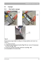
Page 41: ...ueegee daily for soiling and foreign particles and clean it as required 1 Turn off the machine 2 Loosen the two star shaped handles Fig 16 1 and remove the squeegee from the rear Fig 16 2 3 Clean the...

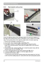
Page 42: ...3 From above press on the slightly unscrewed star shaped handles Fig 17 2 to allow the plastic body with the sealing strips to be removed more easily 4 Unscrew both star shaped handles and remove the...

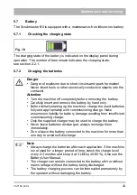
Page 43: ...up the machine charge the used batteries fully and appropriately with commissioning charge Hako assumes no liability for battery damage resulting from insufficient commissioning charge Only the suppli...

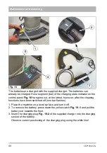
Page 44: ...latest however after the cleaning functions have been switched off one bar flashes 1 Place the machine on a level surface and turn it off 2 To remove the battery press down the yellow catch Fig 19 1...

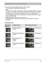
Page 45: ...ing The battery and charger are in the recharging phase The charging process is only complete when the green LED on the charger lights up permanently 5 Installation of the battery is in reverse order...

Page 46: ...46 05 7150 00 fm Maintenance and servicing All LEDs light up Charging process not yet completed Recharging phase LED flashes Charging process completed LED lights up constantly...

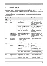
Page 47: ...ate overload protec tion of the electronics Turn the machine off wait 5 minutes if neces sary and then restart it Avoid an excessively rough floor Noise devel opment at the cleaning tool Cleaning tool...

Page 48: ...he ser vice code Service interval expired See maintenance plan 5931 Battery fault Communication error Contact the customer service 5971 5972 Battery fault Contacts on the battery are bent Contact the...

Page 49: ...rective 2006 42 EC as well as the requirements according to 2014 30 EC and 2014 53 EC The following standard s and technical specifications was were referred to for the correct implementation of the s...

Page 50: ...Hako GmbH Head Office Hamburger Str 209 239 23843 Bad Oldesloe Germany Tel 49 4531 806 0 info hako com www hako com...

Reviews: