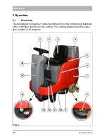
background image

02-7175-00-00.fm

27

Operation

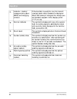
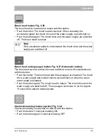
Brush head button Fig. 5-36

The brush head is lowered and raised with this button.
• Push the button: The brush head is lowered. When actuating the 

accelerator pedal, the brush drive and the water supply are switched on.

• Push the button again: The brush drive and the water supply are switched 

off. The brush head is raised.

Brush head and squeegee button Fig. 5-37 (Hakomatic button)

The brush and suction turbine drive are switched on and off simultaneously 
with this button.
• Push the button: The brush head and the squeegee are lowered. The brush 

drive, water supply and suction turbine are switched on when the accel-
erator pedal is actuated.

• Push the button again: The brush head is raised. The brush drive and the 

water supply are switched off. The squeegee continues to run for approx. 
15 seconds to absorb residual water.

Chemical metering button (option) Fig. 5-34

Chemical metering is switched on and off with this button.
• Push the button: Chemical metering ON
• Push the button again: Chemical metering OFF

Note

If the accelerator pedal is not actuated, the brush drive and the water 

supply are switched off.

Summary of Contents for Scrubmaster B75R

Page 1: ...Scrubmaster B75 R 7175 Operating Manual Issue 09 2015 Book number 88 00 3046 Cleaning Technology Municipal Technology...

Page 2: ...ns all important information for operation maintenance and care We have provided the places in this operating manual concerning your safety with a danger pictogram Your authorised Hako dealer is avail...

Page 3: ...on distributed by us to the usual health and safety requirements of the EC Directives see Declaration of Conformity This declaration loses its validity in the event of a modification to the machine no...

Page 4: ...he damage confirmed by the transport company and send in the damage report together with the consignment note to us Machine data Your machine is described clearly by the following data Please always q...

Page 5: ...anel 23 2 2 Controls and display elements 25 2 2 1 Control panel 25 2 2 2 Controls at the machine 29 2 3 General principle of operation 31 2 3 1 Solution tank 31 2 3 2 Brush head 31 2 3 3 Squeegee 32...

Page 6: ...batteries 55 5 3 11 Disposing of batteries 55 5 4 Solution tank 56 5 4 1 Filling the solution tank 56 5 4 2 Emptying the solution tank 57 5 4 3 Cleaning the solution tank 58 5 4 4 Cleaning the fresh...

Page 7: ...al metering system 71 5 8 2 Working spotlight 72 5 8 3 Warning device forwards gear 72 5 8 4 Coarse dirt sieve of waste water tank 72 5 8 5 Wiper and squeegee 760 73 5 8 6 Tray 73 5 8 7 Automatic fill...

Page 8: ...th average risk in which death or severe physical injury can occur if it is not avoided Caution Indication of a danger with low risk in which light to medium severe physical injury or material damage...

Page 9: ...ched to the machine provide important information for safe operation Renew labels that are no longer legible or present With AntiBac machine variants the plastic inner surface of the fresh water and w...

Page 10: ...wing cigarettes The collection of wood dust e g beech and oak dust is also prohibited health hazard For reasons of safety the driver s seat is equipped with a seat contact switch The machine can only...

Page 11: ...th the accident prevention regulations at appropriate intervals we recommend at least once yearly Spare parts must at least comply with the technical requirements specified by the manufacturer This is...

Page 12: ...ucted maintenance personnel must handle and replace batteries Only batteries approved by Hako may be used at the intended position Danger Make sure that the insulation of the battery cables is not dam...

Page 13: ...s plug into the socket when the floor is wet or damp Never dip the mains cable or mains plug in water or other liquids or clean it under running water Damp mains plugs or mains plugs that have become...

Page 14: ...ater and cleaning agents also see the German Water Resources Law WHG Used batteries with the recycling symbol contain reusable commodities In accordance with the symbol showing the crossed out garbage...

Page 15: ...tions 1 7 Labels on the machine The following safety and instruction labels are affixed to the machine in a clearly visible and legible manner Attention Renew missing or illegible labels immediately A...

Page 16: ...Type plate Fig 1 B The type plate is located on the left hand side of the chassis in front of the rear wheel Labels Read and observe the operating manual Fig 1 C1 Maximum permissible slope 2 Fig 1 C2...

Page 17: ...l Explosive gases Fig 1 F The label is located on the right hand side of the battery compartment Label Maintenance parts yellow dot Fig 2 G The yellow dot is located on the cover of the fresh water fi...

Page 18: ...2 1 Overviews The description in chapter 2 contains information on the function and handling of the individual controls on the vehicle The controls always have the same item number in all chapters Fig...

Page 19: ...Cover with vacuum system 5 Filling opening solution tank 6 Level indicator solution tank 7 Solution tank 8 Foot lever brush decoupler 9 Brush head 10 On board chemical metering system option 11 Parkin...

Page 20: ...20 02 7175 00 00 fm Operation Fig 4 23 22 21 25 24 26 27 28 30 32 31 19 17 18 20 29...

Page 21: ...ion 20 Maintenance opening solution tank 21 Adjusting lever fresh water metering 22 Accelerator pedal 23 Wiper option 24 Fresh water filter 25 Squeegee 26 Drain hose waste water 27 Manual suction tool...

Page 22: ...ton brush head 37 Button brush head and squeegee 38 Button speed reduction forwards gear 39 Driving direction selector switch 40 Key switch 41 Button signal horn 42 Button warning device forwards gear...

Page 23: ...tor for Fleet Recorder option Counter for brush decoupling 48 Speed reduction The symbol is displayed when the machine is driving at reduced speed 49 Operating brake Parking brake The warning symbol a...

Page 24: ...number field see section 3 6 53 Brush head The symbol is displayed when the brush head is lowered 54 Suction turbine drive The symbol is displayed when the suction tur bine drive is switched on After...

Page 25: ...on is displayed for approx 1 second in the number field Fig 6 47 possibly followed by the last service code for approx 3 seconds The operating hours meter is then displayed The current charging state...

Page 26: ...n turbine switched on and off with this button Push the button The squeegee is lowered and the suction turbine switched on Push the button again The squeegee is raised The symbol for the suction turbi...

Page 27: ...ff simultaneously with this button Push the button The brush head and the squeegee are lowered The brush drive water supply and suction turbine are switched on when the accel erator pedal is actuated...

Page 28: ...43 The working spotlights can be switched on and off with this button Push the button Working spotlights ON Push the button again Working spotlights OFF Brush decoupling button Fig 5 44 only 7175 1x...

Page 29: ...sassembled quickly and without tools Locking lever parking brake Fig 7 11 The parking brake stops the machine from rolling away accidentally Engage the parking brake 1 Push down the operating brake Fi...

Page 30: ...ator pedal is used to drive forwards or reverse and continuously adjust the speed at the same time If the accelerator pedal is released it automatically returns to the zero position and the machine st...

Page 31: ...n tank The solution tank Fig 9 5 is filled via a hinged opening The solution tank has a capacity of 75 litres The level can be determined via a transparent hose Fig 9 6 Fresh water metering can be set...

Page 32: ...checkout areas the squeegee can be removed by loosening the star shaped handle and hooked into the cover Fig 10 A of the waste water tank 2 3 4 Waste water tank The vacuumed waste water is conveyed v...

Page 33: ...esulting from insufficient commissioning charge Before the machine is initially put into service install the country specific Hako mains cable Check the machine for operating safety before every start...

Page 34: ...the mains plug Fig 11 D straight and firmly into the holder 5 Reinstall the cover using the available screws 3 3 2 Adjusting the driver s seat The driver s seat can be adjusted to three positions 1 O...

Page 35: ...brake and actuate the accelerator pedal The brushes and water supply are switched on 5 Adjust the fresh water quantity as required using the adjusting lever of the fresh water metering system Attenti...

Page 36: ...on The machine slows down to standstill A better braking effect is achieved when the machine is slowed down by applying the brake 2 Bring the driving direction selector switch to the zero position 3 S...

Page 37: ...the key and engage the parking brake 3 Empty and flush the waste water tank 4 Check the fresh water filter adjusting lever for fresh water metering must be set to 0 5 Check the sealing strips and suc...

Page 38: ...ing and rolling away Tie the machine down tightly To do this use tension belts to secure the machine on the supports Fig 13 10 at the front and on the eyes Fig 13 A at the rear Attention When loading...

Page 39: ...hes for foreign particles and remove them if necessary 1 2 6 3 Brush lift system brush and suction turbine have been switched off Foreign particles between brush head and machine Foreign particles bet...

Page 40: ...s Drive motor overheats Remove foreign particles Let the engine cool down 3 6 6 4 Driving and clean ing not possible Seat permanently loaded Relieve seat 5 8 7 0 Batteries are not being charged Cables...

Page 41: ...chine mm 1215 1215 1215 Brush head mm 550 650 650 Squeegee mm 760 860 860 Weight empty without batteries kg 234 244 244 Total weight ready for use kg 377 max 453 389 Driving speed transportation forwa...

Page 42: ...rush contact pressure kg 29 35 35 Air quantity m3 h 110 110 110 Vacuum maximum mbar 170 170 170 Nominal voltage V 24 24 24 Nominal output max P1 W 1800 2520 2520 Power consumption drive motor P1 S2 40...

Page 43: ...customary conditions of use according to DIN EN 60335 2 72 is dB A 61 Measuring uncertainty KpA dB A 3 5 Under the customary conditions of use the weighted effective value of the acceleration to which...

Page 44: ...sults Please always state the serial number in all enquiries and spare parts orders see section 1 7 type plate Hako system maintenance The Hako system maintenance specifies in single modules the speci...

Page 45: ...operating hours Workshop stamp performed on at _______________ operating hours Hako system maintenance I 875 operating hours Workshop stamp performed on at _______________ operating hours Hako system...

Page 46: ...agent Check the squeegee clean if necessary Check the drain hose of the waste water tank for soiling clean if necessary Weekly Clean the machine as required Check the sieve insert in the fresh water f...

Page 47: ...ar wheel mounting screws re tighten if necessary 42 Nm Check the condition of tyres Check correct functioning of the operating and parking brake readjust if necessary Check the electrical system light...

Page 48: ...mage and firm seating replace if necessary Check the drain hose of the waste water tank replace if necessary Check the suspension and bearing assembly of the wheel motor for ease of movement replace w...

Page 49: ...ve been approved by Hako correspond ing settings must be carried out in the configuration menu These settings should only be carried out by a workshop authorised by Hako Variant Type of battery Connec...

Page 50: ...Checking the charging state During operation the charging state of the batteries is displayed in the display panel Fig 14 51 Different numbers of fields are displayed depending on the charging state...

Page 51: ...on due to short circuits and spark formation Never place tools or other electrically conductive objects on the battery Attention Before initially starting up the machine charge the used batteries full...

Page 52: ...y Fields 1 and 2 permanently ON running lights in fields 3 and 4 Main charge 50 charged battery capacity Fields 1 2 and 3 permanently ON field 4 flashes Recharge All fields permanently ON End of charg...

Page 53: ...emains connected to the quick charger Change over from quick to normal charging takes place automati cally Charge the batteries fully after completing the daily cleaning tasks 5 3 7 Table charging tim...

Page 54: ...During the charging process the battery charging status is displayed in the display Fig 16 D of the quick charger In the meantime the charging con trol indicator Fig 14 51 in the display panel is not...

Page 55: ...nstructions and disposal Attention Only use batteries approved by Hako at the intended position Only Optima YellowTop S4 2 must be used for variant 7175 30 otherwise the battery might be damaged Only...

Page 56: ...ine on a level surface 2 Remove the insert of the filling opening Fig 18 A 3 Fill the solution tank up to the maximum 1 1 mark Fig 17 6 maximum water temperature 50 C 4 Add detergent according to the...

Page 57: ...the adjusting lever of the fresh water metering system as far as possi ble The solution tank is emptied via the fresh water filter Emptying the solution tank via the maintenance opening Position the...

Page 58: ...adjusting lever of the fresh water metering system as far as possible 6 Switch on the suction turbine via button Fig 20 35 The fresh water is conveyed into the waste water tank 5 4 3 Cleaning the solu...

Page 59: ...4 weekly and clean or replace it as required 1 Set the adjusting lever of the fresh water metering system Fig 19 21 to 0 2 Turn and remove the filter cover Fig 21 A 3 Remove the filter sieve Fig 21 B...

Page 60: ...ired or when an acoustic signal is output increased suction turbine speed 1 Drive to a suitable disposal centre 2 Position the machine ensuring the drain hose Fig 23 26 reaches the drain in the ground...

Page 61: ...er tank Clean the waste water tank daily or as required 1 Empty the waste water tank see section 5 5 1 2 Open the tank cap Fig 24 4 of the waste water tank Put one hand in the recessed grip Fig 24 A o...

Page 62: ...t the drain hose Check the function of the gasket at the drain hose Fig 25 A daily replace it after 125 operating hours at the latest After use check the drain hose for soiling and clean if necessary...

Page 63: ...aily or as required 1 Decouple the brush see section 5 6 3 2 Thoroughly clean the brush under running water 3 Couple the brush see section 5 6 4 Note If the brush head has two brushes make sure that t...

Page 64: ...he brushes Variant 7175 1x To decouple the brush push button Fig 27 44 for approx 5 seconds until the four consecutively flashing symbols in the display panel have gone out After the brush has been de...

Page 65: ...nt 7175 2x 30 1 Place the brush underneath the brush head holder 2 Raise the brush and push it firmly into the holder Fig 28 3 Turn the brush 360 and push by hand until it engages fully 5 6 5 Replacin...

Page 66: ...height adjustment of the sealing strips 5 7 1 Cleaning the squeegee Check the squeegee Fig 30 23 daily for soiling and foreign particles and clean it as required 1 Pull out the suction hose Fig 30 28...

Page 67: ...needs replacing 1 Pull out the suction hose Fig 30 28 2 Loosen the star shaped handles Fig 30 A and remove the squeegee 3 Press together the protective caps Fig 31 I and pull them out 4 Loosen the cla...

Page 68: ...ee 2 Loosen the lock nuts Fig 30 D and turn the threaded bar Fig 30 E to adjust the squeegee ensuring both ends of the sealing strips barely have contact with the ground Turn the threaded bar counter...

Page 69: ...ion adjust ment set the distance of the supporting rollers to the lower edge of the sealing strip by adjusting the number of washers under the supporting roller holder Number of washers Distance to th...

Page 70: ...On board chemical metering system 7678 30 14 Working spotlight 7092 50 16 Warning device forwards gear 7091 50 19 Coarse dirt sieve 7060 50 23 Wiper and squeegee 760 7176 05 27 Hand suction tool incl...

Page 71: ...rey cover Fig 36 C at the dosing pump 2 Set the mixing ratio according to the used cleaning chemicals 3 Basic setting 1 700 Set the rotary knob between stage 1 and 2 see the table Maintenance Check th...

Page 72: ...g device forwards gear When activating the warning device forwards gear the warning lamp flashes and an acoustic signal is output Use the button to toggle between two options Push the button once Warn...

Page 73: ...e side If the wiper is not required it can be hooked at the intended position using the locking lever Fig 37 B Maintenance Maintenance and servicing squeegee see section 5 7 Check the rubber of the wi...

Page 74: ...low 4 The filling unit switches off automatically when the tank is full The indicator knob Fig 38 C no longer protrudes 5 Close the water supply and remove the water connection Use a water line fitted...

Page 75: ...option deviating machine functions depending on the respective customer configuration possible Ending operation 1 Turn off the machine with the key switch Optional Indicator LED Machine function Data...

Page 76: ...equirements of the EC Directive 2006 42 EC as well as the require ments according to 2004 108 EC The following standard s and technical specifications was were referred to for the correct implementati...

Page 77: ...77...

Page 78: ...rt ex press and on call ser vice guarantees best possible availability Close to you wherever you are Our efficient close knit sales service network guarantees close proxi mity and rapid help Cleanline...

Reviews: