background image

38

Operation

Cab (optional)

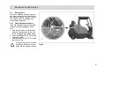
Swinging the cab up

The cab can be swung up for mainte-

nance work. Please follow the order 
described below, since otherwise the 

cab or machine may be damaged.

1. Switch the engine off and close the 

cab door.

2. Open the side flap and fit the pump 

lever onto the hand pump (Fig. 21/1).

3. Set the control lever (Fig. 21/2) on 

the pump to "raise" (arrow upwards) 

and pump the cab up with the pump 
lever until it moves no further.

4. Pull off the pump lever, place it in the 

holder and close the side flap again.

Fig.21

1

2

Summary of Contents for Sweepmaster B1500 RH

Page 1: ...Instruction Manual Sweepmaster B1500 RH 6464 40...

Page 2: ...modification as re quired by technical advancement Valid as of April 2014 Hako GmbH D 23843 Bad Oldesloe Hamburger Str 209 239 Phone 49 0 4531 8060 Proper use The Sweepmaster is a sweeping in tended f...

Page 3: ...ycling sym bol contain reusable commodities The heavy metals contained simultaneously represent a serious risk to health and to the environment Never open batteries or damage them Never touch inhale o...

Page 4: ...registration office applies the applicable stamp Driving license In accordance with the provisions on driving licenses a person who intends to drive a motor vehicle constructed with a top speed in ex...

Page 5: ...maintenance 43 5 2 Maintenance report 44 5 3 Maintenance plan 45 5 4 Seat console 51 5 4 1 Opening the seat console 51 5 5 Battery system 52 5 5 1 Total discharge signal transdu cer TSG 53 5 5 2 Charg...

Page 6: ...efinition Safety information persons or property Safety information on preventing hazardous situations caused by failure to follow instructions or prescribed working procedures accurately or at all No...

Page 7: ...ensure safety It is forbidden to move into the haz ard area of the vehicle A mobile phone may only be used when the vehicle has been stopped It is forbidden to transport people on the vehicle 1 3 Ope...

Page 8: ...es with a gradient steeper than the limit gradient indicated on the vehicle The approved gross total weight and permissible axle loads must never be exceeded Check the fill level of the dirt hopper at...

Page 9: ...t is not permitted to clean the vehicle with a pressure washer or steam blaster When transporting the vehicle the vehicle must be switched off If the Sweepmaster is jacked up with a jack it must be pr...

Page 10: ...es Seek medical attention im mediately in order to prevent the risk of infection Take care when draining hot oil risk of burns Subject the brake system to a thor ough inspection regularly Adjust ments...

Page 11: ...tion in the oper ating manual provided by the battery manufacturer Never lay any metallic objects or tools on batteries risk of short cir cuit Ensure sufficient ventilation in the charging area when c...

Page 12: ...Company logo Fig 1 1 front and rear Rating plate Fig 1 2 Vehicle identification number Fig 1 3 Machine model Fig 1 4 Parking brake Fig 1 5 Read and observe the operating manu al Fig 1 6 High pressure...

Page 13: ...13 Safety Information Fig 1 10 1 1 8 3 6 5 7 9 2 4 11 12...

Page 14: ...14 Safety Information Brush wear compensation Fig 2 1 Keep clear of dirt hopper Fig 2 2 Hydraulic oil Fig 2 3 Risk of crushing by dirt hopper Fig 2 4...

Page 15: ...15 Safety Information Fig 2 1 2 4 3...

Page 16: ...ore putting the machine into service Only technicians from your local autho rized Hako dealer are allowed to pro vide initial instruction on the machine The manufacturing plant will notify the dealer...

Page 17: ...s and tanks must show no signs of leaks or damage 2 Check the battery charge status Fig 3 1 charge the battery if nec essary 3 Check the hydraulic oil level in the hydraulic tank Fig 3 2 refill if nec...

Page 18: ...rt ed when the operator is sitting on the driver s seat The function of the seat contact switch must not be by passed The seat contact switch is monitored electronically Any attempt at manip ulation c...

Page 19: ...he vehicle s parking brake must be applied Fig 4 2 3 Connect the battery plug Fig 4 3 to the device connector 4 Turn the key switch Fig 4 4 The operating hour counter Fig 4 A displays the software ver...

Page 20: ...ng The vehicle slows down to a stop 2 Apply the parking brake Fig 5 2 to its end position and lock in place 3 Switch off the sweeping functions with the button Fig 5 A 4 Switch off the vehicle with th...

Page 21: ...activated 4 In the case of damp waste switch the suction turbine off with the button Fig 6 B 5 Release the parking brake Fig 6 2 to its end position 6 Slowly press the accelerator Fig 6 3 until the r...

Page 22: ...on a horizontal surface Before raising the dirt hopper the operator must have ensured that there are no persons or objects be hind or beside the vehicle The vehicle may only be driven slow ly when th...

Page 23: ...t hopper To do this press and hold the button Fig 7 A until the hopper is lifted to the height required 4 Drive backwards slowly Empty the dirt hopper To do this press and hold the button Fig 7 B unti...

Page 24: ...6 1 Rotary brush stops engine is switched off sweep ing is switched off Foreign bodies tape or such is blocking the rotary brush motor is briefly overloaded Check the rotary brush for foreign bodies...

Page 25: ...ot dirt hopper function switched off individually or all A safety fuse on module 3E Code B A3 is defective Replace the defective fuse 3 1 6 7 All functions controlled via modules 3E CA B fail A safety...

Page 26: ...he vehicle using straps at both front lashing points Fig 8 1 and the two rear lashing points Fig 8 2 which are located in the wheel case 2 8 Towing the vehicle Towing distance Max 500 m to move the ma...

Page 27: ...ecincts Sweeping The side brush Fig 9 1 sweeps the dirt directly into the pick up path Fig 9 2 of the rotary brush Fig 9 2 The ro tary brush sweeps the dirt overhead Fig 9 3 into the sweeping containe...

Page 28: ...harge status indicator 7 Not used 8 Button to raise the dirt hopper 9 Button to pivot the dirt hopper for emptying 10Button to pivot the dirt hopper back 11 Button to lower the dirt hopper 12Button fo...

Page 29: ...itching the ignition on If the display flashes it means the driver s seat is not occupied A list of possible errors is provided in Section 2 6 1 Charge status indicator Fig 10 6 After switching on the...

Page 30: ...use it can only be lowered when in a horizontal position The con trol lamp in the button lights up Button to lower the dirt hopper con tainer Fig 10 11 It serves to lower the dirt hopper To lower the...

Page 31: ...bine is in the switching on or off phase Switch the suction turbine off in the case of wet waste Button for rotary brush Fig 10 14 It serves to switch the rotary brush on and off When the rotary brush...

Page 32: ...witch 2 Not used 3 Not used 4 Horn switch 5 Switch for parking light driving lights option 6 Switch for hazard lights option 7 Switch for flashing beacon option 8 Switch for drive direction indicator...

Page 33: ...shes Switch for horn Fig 11 4 An acoustic signal is issued on actuat ing the switch Switch for parking light driving lights option Fig 11 5 The switch serves to switch the parking light driving lights...

Page 34: ...drive Fig 12 Service brake and parking brake The service brake Fig 13 1 actuates the mechanical drum brakes which act on the two rear wheels Before getting off the vehicle apply the parking brake and...

Page 35: ...6 1 is used to set the sweeping pattern of the rotary brush Refer to Chapter Maintenance and Service for information on setting the sweeping pattern Fig 16 Locking the seat console For reasons of safe...

Page 36: ...e of the dirt hopper can be monitored through the opening Fig 18 1 Fig 18 Filter system lock The filter system is above the dirt hop per The cover of the filter system is se cured by the lock Fig 19 1...

Page 37: ...s released by means of the lever B and can be adjusted in a longitudinal direction For reasons of safety the vehi cle is equipped with a seat con tact switch The vehicle can only be started when the o...

Page 38: ...hine may be damaged 1 Switch the engine off and close the cab door 2 Open the side flap and fit the pump lever onto the hand pump Fig 21 1 3 Set the control lever Fig 21 2 on the pump to raise arrow u...

Page 39: ...down wards and pump the cab down with the pump lever until it moves no fur ther 4 Pull off the pump lever place it in the holder and close the side flap again Switch for wiper The wiper is switched o...

Page 40: ...ight kg 1560 Permissible total weight kg 2350 Driving and sweeping performance Driving speed forwards kph 0 8 Driving speed reverse kph 0 4 Max sweeping speed kph 8 Theoretical sweeping performance wi...

Page 41: ...diameter width mm 310 120 Tires rear CSE 4 00 8 Hydraulic system Hydraulic oil e g Mobiloil DTE 25M or DTE 10 Excel46 Tank volume Liter 1 5 Electrical installation Voltage V 36 Max battery capacity A...

Page 42: ...ditions is dB A 91 The sound power level LwAd measured according to 2000 14 EC under normal working conditions is dB A 91 Vibration values The weighted effective value of the acceleration established...

Page 43: ...specific technical work nec essary for the individual modules and defines the intervals for the mainte nance tasks Individual parts which must be changed during maintenance tasks are defined and stip...

Page 44: ...ating hours Hako System Maintenance III 1000 operating hours Workshop Stamp completed on at _________________ operating hours Hako System Maintenance I 1250 operating hours Workshop Stamp completed on...

Page 45: ...level fill distilled water if necessary only towards the end of the charging process o Check the rotary brush for foreign bodies e g wire tape etc o Function test of the parking brake o Check the tire...

Page 46: ...wear readjust or change as necessary o Check the function of the steering o Check the filter system clean the filter as necessary o Check the function of the agitating device o Check the dirt hopper s...

Page 47: ...r wear and foreign bodies e g wire tape etc o Check the control lamps acoustic warning signals lighting system and seat contact switch of the electric system o Check the function of the parking brake...

Page 48: ...charging process o Clean and grease the battery poles o Check the properties of the fan belt change if necessary o Check the dirt hopper seals replace as necessary o Check the side brush for signs of...

Page 49: ...ordance with Hako system maintenance I o Change the hydraulic oil o Change hydraulic oil filter o Check the rotary brush and side brush change if necessary o Change the sealing strips o Clean the carb...

Page 50: ...vity Interval Every 1000 operating hours All maintenance work in accordance with Hako system maintenance I and II o Check the retaining screws retighten as necessary safety check o Check the carbon br...

Page 51: ...ing the seat console If the cab safety roof option is installed the seat console is equipped with a lock 1 Park the vehicle on a level surface Switch off the vehicle with the key switch and apply the...

Page 52: ...system option 5 Connector 6 Brackets The illustration depicts the PzS trough battery set 36V 450 Ah option In order to fix the bat tery cable there are two brack ets and cable ties enclosed with the b...

Page 53: ...atteries must be charged immediately Open the seat cover during the charging process 1 Park the vehicle on a level area of floor 2 Switch the vehicle off and apply the parking brake 3 Open the side do...

Page 54: ...accordance with the connection diagram see figure 5 Sparking may occur when con necting the batteries Ensure they are connected firmly Risk of injury 6 Connect the battery plug Fig 24 2 to the device...

Page 55: ...ystem Work on the hydraulic system may only be carried out by technical experts and corre spondingly trained personnel Hydraulic oil under high pres sure can cause severe injuries 1 Hydraulic oil filt...

Page 56: ...ic pump Allow the hy draulic oil to drain off into the collect ing vessel Dispose of the used hydraulic oil according to the applicable environmental regulations 4 Fix the hydraulic hose to the hydrau...

Page 57: ...57 Maintenance and Service 5 7 Sweeping unit 1 Side brushes 2 Rotary brush 3 Sweepings container 4 Suction turbine 5 Filter system Fig 26 1 2 3 4 5...

Page 58: ...58 Maintenance and Service 5 7 1 Side brushes 1 Adjusting bolt 2 Side brushes 3 Catch Fig 27 2 1 3...

Page 59: ...of the side brush Fig 27 2 using the adjusting bolt Fig 27 1 The contact surface of the side brush should be approx 2 3 of the brush circumference 5 7 3 Changing the side brushes When the brushes have...

Page 60: ...Rotary brush 1 Rotary brush 2 Sealing strip left 3 Sealing strip front 4 Sealing strip rear 5 Sealing strip right 6 Rotary brush half 7 Screw connection 5 pieces 8 Crank for rotary brush adjustment 9...

Page 61: ...f the parallel alignment is no longer set please contact an autho rized Hako service center 5 7 7 Changing the rotary brush In the case of wear resulting in a bristle length of at least 100 mm the rot...

Page 62: ...using an actuating rod The sealing strip must make contact with the floor and bend slightly to the rear 6 The rear sealing strip Fig 28 4 can be adjusted via the slots The sealing strip must have a c...

Page 63: ...63 Maintenance and Service 5 7 10 Filter system 1 Lock 2 Cover 3 Holder 4 Wing bolt 5 Frame 6 Agitating device 7 Dust filter Fig 29 1 2 3 4 6 4 4 4 5 7...

Page 64: ...ating device Fig 29 6 and allow it to engage in the holder Fig 29 3 4 Remove the dust filter Fig 29 7 5 Drop the dust filter horizontally onto level ground from a height of approx 1 meter soiled side...

Page 65: ...ion key 3 Bring the jack Fig 30 1 into posi tion under the frame 4 Raise the vehicle with the jack 5 Remove the nut and the washer 6 Remove the tires with rims 7 Mount new tires Only use original spar...

Page 66: ...ery F1 Main fuse 200A F2 Pre fuse 50A F3 Indicator 10A option F4 Spare F5 RKL 12V 7 5A option F6 Parking Rear light right 5A op tion F7 Parking Rear light left 5A option F8 Driving lights 15A F9 DC DC...

Page 67: ...lic motor K3 Changeover relay driving direction forwards reverse K4 Relay Driving lights 24V or Relay working lights 24V option K6 Relay 24V windscreen wipers K8 Indicator relay option A Drive control...

Page 68: ...436 Lighting system To acquire a vehicle type approval in accordance with StVZO road traffic licensing regulation 643136 Flashing beacon On pole for installation without cab safety roof 12 Volt 643302...

Page 69: ...in accordance with 2004 108 EC Reference was made to the following standards and or norms and or techni cal specifications to ensure proper im plementation of the safety and health requirements in the...

Page 70: ...entechnik f r eine saubere und sch nere Umwelt Advanced Technology for a Cleaner Better Environment Hako GmbH Hamburger Str 209 239 D 23843 Bad Oldesloe 49 4531 806 0 Fax 49 4531 806 338 88 10 2943 31...

Reviews: