background image

8

Controls

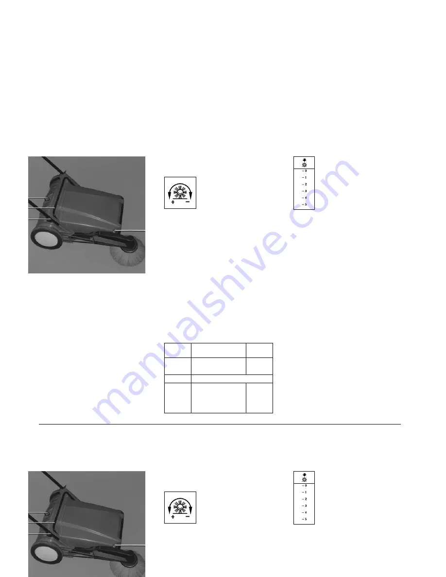
1 Handwheel for sweeping roller

adjustment

is used for adjustment of the swee-
ping roller ground pressure.
The sweeping roller ground pres-
sure should be adjusted as recom-
mended by us, or be adapted to
local conditions, until good swee-
ping performance will be achieved.
Adjustment is indicated by the
scale close to the track wheel.

Recommended adjustment

(valid for sweeping roller in ”as
new“ condition“)Basic adjustment:
Scale code 1.5

1  handwheel for sweeping roller

adjustment

2 hopper handle
3  butterfly nuts for fixing of handlebar
4  handwheel with knurled nut for side

brush adjustment

Note: 

Sweeping roller ground pres-

sure, if adjusted to too high a
value, requires higher physical
force to push the machine, and
increases the wear of brooms. Best
sweeping performance will be
achieved at 
2.5 m.p.h. = 4 km.p.h., i. e. normal
pedestrian’s speed.

2 Hopper handle

is used to remove the dust hopper.

3 Butterfly nuts for fixing

of handlebar

are used to secure the handlebar.

I

Scale

litter

ground

code

1

light-weight,

unruffled

dry litter

1.5

basic adjustment

2

heavy dirt, or big

rough

dirt quantities;

or

humid or sticky

uneven

dirt

1
2

3

1

Summary of Contents for Sweepmaster M600

Page 1: ...OTUSVDUJPO BOVBM Instruction Manual Sweepmaster M600...

Page 2: ......

Page 3: ...ttach handlebar 15 Attach side broom 16 Operating the Sweepmaster M600 17 Controls 18 Emptying the dirt hopper 19 Insert the dirt hopper 19 Replacement of main broom 10 Side broom 11 Replacement of si...

Page 4: ...by the Railway Officer or by the Forwarding Agent and send the statement of damage together with the bill of lading to Hako GmbH Hamburger Stra e 209 239 D 23843 Bad Oldesloe It is our desire that th...

Page 5: ...e the wing bolts A 1 Note The handlebar can be mounted in two positions as suitable for the operators tallness For short people Install the handlebar with handle rod bent to downside For average and b...

Page 6: ...h more than 2 3 of its circumference Secure with knurled check nut B C D Attach side broom Unpack side broom arm and broom Plug side broom on broom shaft and secure with bolt use 10 mm spanner size Do...

Page 7: ...rear end of the machine This means that all usual obstacles are overcome by pulling the machine uphill or pushing it down hill The handlebar is folding to ease transportation or storage of the Sweepm...

Page 8: ...igh a value requires higher physical force to push the machine and increases the wear of brooms Best sweeping performance will be achieved at 2 5 m p h 4 km p h i e normal pedestrian s speed 2 Hopper...

Page 9: ...ft the dirt hopper just use the handle provided Insert the dirt hopper Locate the hopper on the forward frame as shown and slue down Note Do not place the dirt hopper flat on ground to avoid damage to...

Page 10: ...h 480 mm 18 9 Dia 250 mm 9 8 Dia wear limit approx 180 mm 7 1 The broom roller is replaced as follows Slue side broom up Tilt machine back to rest on the handlebar Remove three ea Phillips screws turn...

Page 11: ...machine Adjust tension of side broom Vee belt To tension the Vee belt proceed in the following way Slue up side broom Loosen bolts B 2 should come out approx 5 mm 0 2 Lift roller holder B 1 from slot...

Page 12: ...ft Fit new Vee belt on pulley and re assemble reverse the above pro cedure Note After having assembled the pulley check for key in place refer to sketch right above Check Move Vee belt to the right sh...

Page 13: ...ers into the slots marked by arrows and remo ve the hub cap using the screwdri ver as a lever applying force in a uniform manner fig A Then remove the circlip from the wheel axle and remove the track...

Page 14: ...40 11 02 x 1 57 swept width w o side broom mm 480 18 9 swept width with side broom mm 670 26 38 broom roller dia mm 250 9 84 broom roller width mm 480 18 9 min dia of roller broom mm 180 7 09 broom s...

Page 15: ...very 6 months grease axles of track wheels and pinions check drive belt tension re adjust as required Maintenance work Compliance with the maintenance work recommended by Hako will make sure that your...

Page 16: ...Advanced Technology for a Cleaner Better Environment Hako GmbH Hamburger Str 209 239 23843 Bad Oldesloe Germany Phone 49 4531 806 0 Fax 49 4531 806 338 88 10...

Reviews: