


HAKUBA 26PPM Laser Printer - Base Engine Technical Manual
6-9
Version 1.0
Secondary FIPs
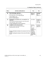
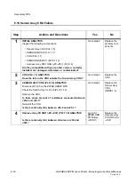
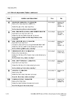
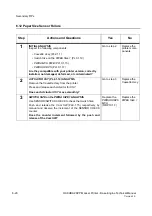
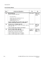
6.4 Heat Rod Failure continued
Step
Actions and Questions
Yes
No
6
HEAT ROD SIGNAL ANALYSIS
Disconnect J282 from the
HVPS Assy
.
Disconnect P/J27 from the
PWB HKB MCU.
Switch ON Main Power.
Does the Heat Rod glow?
Replace the
ROS Assy
(RRP8.1.5)
Replace the
PWB HKB
MCU
(RRP10.1.7)
7
Harness Assy Fuser-M (J271,J11, J27, J262)
(PL6.1.12)
ANALYSIS
Disconnect the AC power plug from the back of the printer.
Disconnect P/J27, P/J271 and J282.
Is there continuity (0
Ω
)
at the each harness?
Go to step 8
Replace the
Harness Assy
Fuser-M
(J271, J11,
J27, J262)
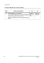
8
THERMOSTAT AND FUSE ANALYSIS
Remove the Fuser Assembly from the printer.
Disassemble the Fuser Assy.
Is there continuity (0
Ω
)
between the two ends of the Ther-
mostat?
Is there continuity (0
Ω
)
between the two ends of the Plate
Fuse?
Go to 6.3
Error Code
U4.
If your are
unable to
determine the
problem,
replace the
Fuser Assy,
PWBA HKB
PS,
and the
PWBA HKB26
MCU
.
Replace the
Fuser Assy
(RRP6.1.3)
Summary of Contents for b 6100
Page 1: ...HAKUBA 26PPM Laser Printer Base Engine Technical Manual Version 1 0...
Page 8: ...viii HAKUBA 26PPM Laser Printer Base Engine Technical Manual Version 1 0 Blank Page...
Page 124: ...8 2 HAKUBA 26PPM Laser Printer Base Engine Technical Manual Version 1 0 Diagnostic Mode...
Page 146: ...8 24 HAKUBA 26PPM Laser Printer Base Engine Technical Manual Version 1 0 Diagnostic Mode...
Page 148: ...9 2 HAKUBA 26PPM Laser Printer Base Engine Technical Manual Version 1 0 Adjustment Mode...
Page 152: ...9 6 HAKUBA 26PPM Laser Printer Base Engine Technical Manual Version 1 0 Adjustment Mode...
Page 396: ...12 26 Hakuba 26PPM Laser Printer Base Engine Technical Manual Version 1 0 Parts List...


