


6-12
HAKUBA 26PPM Laser Printer - Base Engine Technical Manual
Version 1.0
Secondary FIPs
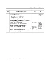
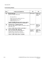
6.7 Sensor Photo:Regi Failure
Step
Actions and Questions
Yes
No
1
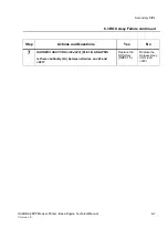
INITIAL ANALYSIS
Inspect the following components.
•
P/H Assy
(PL5.1.4)
•
PWBA HKB26 MCU
(PL10.1.13)
•
Harness Assy Regi (J43-J431, J423)
(PL5.1.28)
•
PWBA HKB PS
(PL10.1.17)
Are they compatible with your printer version, correctly
installed, not damaged, deformed, or contaminated?
Go to step 2
Replace the
problem com-
ponents
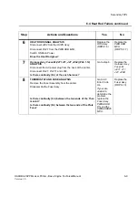
2
SENSOR PHOTO:REGI
(PL5.1.12) POWER ANALYSIS
Check the voltage between P/J43-4 and P/J43-3.
Is there +3.3 VDC between P43-4 and P43-3?
Go to step 3
Go to 6.1
PWBA HKB
PS
Failure
(+3.3VDC)
3
SENSOR PHOTO:REGI
(PL5.1.12) SIGNAL ANALYSIS
Move the
Actuator Regi
(PL2.1.10) by a sheet of paper.
Check the voltage between P/J43-5 and P/J43-4.
Does the voltage between P/J43-5 and P/J43-4 fall down
from +3.3VDC to 0VDC when the
Actuator Regi
is pushed
down by a sheet of paper?
Replace the
PWBA HKB26
MCU
(RRP10.1.7)
Replace the
Sensor
Photo:Regi
(RRP5.1.5)
Summary of Contents for b 6100
Page 1: ...HAKUBA 26PPM Laser Printer Base Engine Technical Manual Version 1 0...
Page 8: ...viii HAKUBA 26PPM Laser Printer Base Engine Technical Manual Version 1 0 Blank Page...
Page 124: ...8 2 HAKUBA 26PPM Laser Printer Base Engine Technical Manual Version 1 0 Diagnostic Mode...
Page 146: ...8 24 HAKUBA 26PPM Laser Printer Base Engine Technical Manual Version 1 0 Diagnostic Mode...
Page 148: ...9 2 HAKUBA 26PPM Laser Printer Base Engine Technical Manual Version 1 0 Adjustment Mode...
Page 152: ...9 6 HAKUBA 26PPM Laser Printer Base Engine Technical Manual Version 1 0 Adjustment Mode...
Page 396: ...12 26 Hakuba 26PPM Laser Printer Base Engine Technical Manual Version 1 0 Parts List...


