


10-6
HAKUBA 26PPM Laser Printer - Base Engine Technical Manual
Version 1.0
Removal and Replacement Procedures (RRPs)
Section 10 - Removal and Replacement Procedures continued
Notations in the RRP text
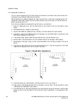
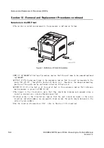
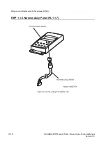
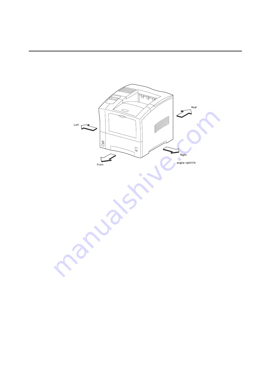
\ The printer orientation expressed in the procedure is defined as follows.
Figure 1. Definition of Printer Orientation
\ RRP X.Y.Z
g AAAAAh at the top of procedure implies that the part name to be removed/replaced
isg AAAAAh .
\g (PLX.Y.Z)h following part name in the procedure implies that this part corresponds to the
plate (PL) g X.Yh , item g Zh in Section 12 Parts List. Therefore, the shape and mounting
position of the parts can be confirmed in Section 12 Parts List.
\g (PPR X.Y.Z.)h in the text or at the end of text in the procedure implies that reference
work procedure is given in g PPR X.Y.Zh .
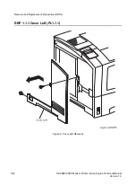
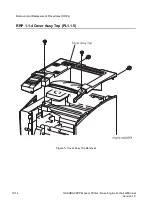
\ The screws in the illustration imply that they should be loosened and removed using a
cross-tip screw-driver, unless otherwise specified.
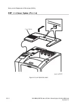
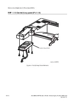
\ A black arrow in the illustration implies that the part should be moved in the arrow
direction, and when numbers are assigned to black arrows, the parts should be moved in the
order of given numbers.
\ For the location of connectors (P/J), refer to [Section 11 P/J Location].
Summary of Contents for b 6100
Page 1: ...HAKUBA 26PPM Laser Printer Base Engine Technical Manual Version 1 0...
Page 8: ...viii HAKUBA 26PPM Laser Printer Base Engine Technical Manual Version 1 0 Blank Page...
Page 124: ...8 2 HAKUBA 26PPM Laser Printer Base Engine Technical Manual Version 1 0 Diagnostic Mode...
Page 146: ...8 24 HAKUBA 26PPM Laser Printer Base Engine Technical Manual Version 1 0 Diagnostic Mode...
Page 148: ...9 2 HAKUBA 26PPM Laser Printer Base Engine Technical Manual Version 1 0 Adjustment Mode...
Page 152: ...9 6 HAKUBA 26PPM Laser Printer Base Engine Technical Manual Version 1 0 Adjustment Mode...
Page 396: ...12 26 Hakuba 26PPM Laser Printer Base Engine Technical Manual Version 1 0 Parts List...


