


HAKUBA 26PPM Laser Printer - Base Engine Technical Manual
10-15
Version 1.0
Removal and Replacement Procedures (RRPs)
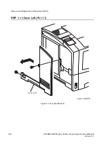
RRP 1.1.4 Cover Assy Top (PL1.1.5) continued
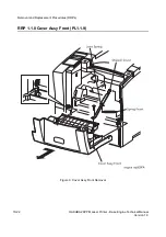
Removal
1. Remove the
Cover Assy Front
(RRP 1.1.8).
2. Remove the
Cover Front L/H
(RRP 1.1.10).
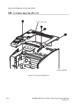
3. Open the
Cover Assy Rear
.
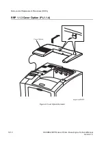
4. Remove the
Cover Option
(RRP 1.1.3).
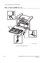
5. Remove the four screws securing the
Cover Assy Top
to the printer.
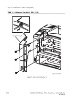
6. Raising a little the
Cover Assy Top
from the printer, unplug the connector (P/J362) on the
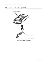
back side of
Control Assy Panel
(PL1.1.6).
7. Remove the
Cover Assy Top
from the printer.
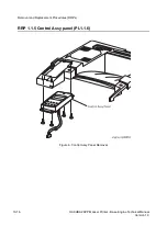
8. Remove the
Control Assy Panel
(RRP 1.1.5).
Replacement
In the following steps, mount the
Cover Assy Top
while paying attention to the
sections overlapped with the
Cover Left
,
Cover Assy I/F
, and
Cover Right
.
1. Mount the
Control Assy Panel
(RRP 1.1.6) on the
Cover Assy Top
(RRP 1.1.5).
2. Plug the connector (P/J362) on the back side of
Control Assy Panel
from the
Cover Assy Top
.
3. Align the
Cover Assy Top
with its mount position on the printer.
4. Secure the
Cover Assy Top
to the printer with four screws.
5. Mount the
Cover Option
(RRP 1.1.3).
6. Close the
Cover Assy Rear
.
7. Mount the
Cover Front L/H
(RRP 1.1.10).
8. Mount the
Cover Assy Front
(RRP 1.1.8).
Summary of Contents for b 6100
Page 1: ...HAKUBA 26PPM Laser Printer Base Engine Technical Manual Version 1 0...
Page 8: ...viii HAKUBA 26PPM Laser Printer Base Engine Technical Manual Version 1 0 Blank Page...
Page 124: ...8 2 HAKUBA 26PPM Laser Printer Base Engine Technical Manual Version 1 0 Diagnostic Mode...
Page 146: ...8 24 HAKUBA 26PPM Laser Printer Base Engine Technical Manual Version 1 0 Diagnostic Mode...
Page 148: ...9 2 HAKUBA 26PPM Laser Printer Base Engine Technical Manual Version 1 0 Adjustment Mode...
Page 152: ...9 6 HAKUBA 26PPM Laser Printer Base Engine Technical Manual Version 1 0 Adjustment Mode...
Page 396: ...12 26 Hakuba 26PPM Laser Printer Base Engine Technical Manual Version 1 0 Parts List...