


HAKUBA 26PPM Laser Printer - Base Engine Technical Manual
10-27
Version 1.0
Removal and Replacement Procedures (RRPs)
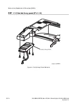
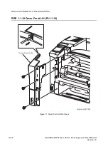
RRP 1.1.10 Cover Front L/H (PL1.1.19) continued
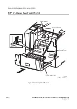
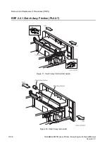
Removal
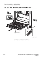
1. Remove the
Cover Assy Front
(RRP 1.1.8).
2. Remove the three screws securing the
Cover L/H
to the printer.
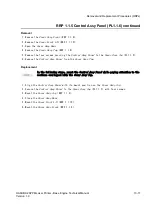
3. Disengage the upper left hook of
Cover L/H
, draw it a little toward the front from the
printer.
4. Remove the
Cover L/H
from the printer.
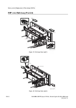
Replacement
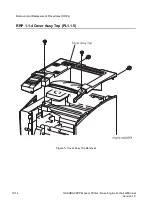
In the following steps, mount the
Cover L/H
while paying attention to the sections
overlapped with the
Cover Assy Top
and
Cover Left
.
1. Aligning the
Cover L/H
with its mount position to the printer.
2. Engage the hook of
Cover L/H
with a hole on the left side of
Cover Assy Top
to secure the
Cover L/H
.
3. Secure the
Cover L/H
to the printer with three screws.
4. Mount the
Cover Assy Front
(RRP 1.1.8).
Summary of Contents for b 6100
Page 1: ...HAKUBA 26PPM Laser Printer Base Engine Technical Manual Version 1 0...
Page 8: ...viii HAKUBA 26PPM Laser Printer Base Engine Technical Manual Version 1 0 Blank Page...
Page 124: ...8 2 HAKUBA 26PPM Laser Printer Base Engine Technical Manual Version 1 0 Diagnostic Mode...
Page 146: ...8 24 HAKUBA 26PPM Laser Printer Base Engine Technical Manual Version 1 0 Diagnostic Mode...
Page 148: ...9 2 HAKUBA 26PPM Laser Printer Base Engine Technical Manual Version 1 0 Adjustment Mode...
Page 152: ...9 6 HAKUBA 26PPM Laser Printer Base Engine Technical Manual Version 1 0 Adjustment Mode...
Page 396: ...12 26 Hakuba 26PPM Laser Printer Base Engine Technical Manual Version 1 0 Parts List...