


HAKUBA 26PPM Laser Printer - Base Engine Technical Manual
10-35
Version 1.0
Removal and Replacement Procedures (RRPs)
RRP 1.2.4 Chute Assy Face Up (PL1.2.8) continued
.
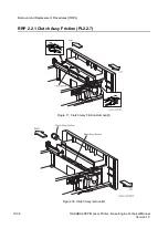
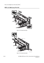
Removal
1. Remove the
Cover Assy Rear Face Up
(RRP 1.2.3).
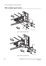
2. Remove the two screws securing the
Chute Assy Face Up
to the
Cover Assy Rear
.
3. Remove the
Chute Assy Face Up
from the
Cover Assy Rear
.
Replacement
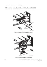
1. Engage the right hole in the
Chute Assy Face Up
with a boss of
Arm Direction
(PL1.2.6) on
the
Cover Assy Rear
(PL1.2.5).
2. Adjust the Chute Assy Face Up to the setting position of the Cover Assy Rear Face Up,and
then fasten it by both screws.
3. Mount the
Cover Assy Rear Face Up
(RRP 1.2.3).
Summary of Contents for b 6100
Page 1: ...HAKUBA 26PPM Laser Printer Base Engine Technical Manual Version 1 0...
Page 8: ...viii HAKUBA 26PPM Laser Printer Base Engine Technical Manual Version 1 0 Blank Page...
Page 124: ...8 2 HAKUBA 26PPM Laser Printer Base Engine Technical Manual Version 1 0 Diagnostic Mode...
Page 146: ...8 24 HAKUBA 26PPM Laser Printer Base Engine Technical Manual Version 1 0 Diagnostic Mode...
Page 148: ...9 2 HAKUBA 26PPM Laser Printer Base Engine Technical Manual Version 1 0 Adjustment Mode...
Page 152: ...9 6 HAKUBA 26PPM Laser Printer Base Engine Technical Manual Version 1 0 Adjustment Mode...
Page 396: ...12 26 Hakuba 26PPM Laser Printer Base Engine Technical Manual Version 1 0 Parts List...


