


HAKUBA 26PPM Laser Printer - Base Engine Technical Manual
10-103
Version 1.0
Removal and Replacement Procedures (RRPs)
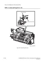
RRP 5.1.1 P/H Assy (PL5.1.4) continued
Removal
1. Remove the
Cover Assy Front
(RRP 1.1.8).
2. Remove the
Cover Front L/H
(RRP 1.1.10).
3. Remove the
Chute MBF Assy
(RRP 4.1.1).
4. Remove the
Shaft 14
(RRP 5.1.10).
5. Remove the
Gear 14
(RRP 5.1.10).
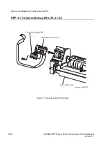
6. Unplug the connector (P/J42) in the
P/H Assy
.
7. Unplug the connector (P/J43) in the
P/H Assy
.
8. Release two clamps on the harness of
P/H Assy
.
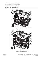
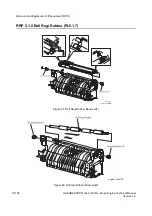
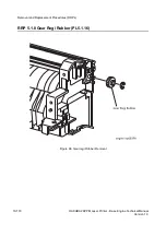
9. Remove the five screws securing the
P/H Assy
to the printer.
10. Raising a little the right end of
P/H Assy
to shift to the right, remove the
P/H Assy
upward from the printer.
Replacement
1. Insert the
P/H Assy
from diagonal right into the printer, and align the position.
2. Secure the
P/H Assy
to the printer with five screws.
3. Secure the harness of
P/H Assy
with two clamps.
4. Plug the connector (P/J42) in the
P/H Assy
.
5. Plug the connector (P/J43) in the
P/H Assy
.
6. Mount the
Gear 14
(RRP 5.1.10).
7. Mount the
Shaft 14
(RRP 5.1.10).
8. Mount the
Chute MBF Assy
(RRP 4.1.1).
9. Mount the
Cover Front L/H
(RRP 1.1.10).
10. Mount the
Cover Assy Front
(RRP 1.1.8).
Summary of Contents for b 6100
Page 1: ...HAKUBA 26PPM Laser Printer Base Engine Technical Manual Version 1 0...
Page 8: ...viii HAKUBA 26PPM Laser Printer Base Engine Technical Manual Version 1 0 Blank Page...
Page 124: ...8 2 HAKUBA 26PPM Laser Printer Base Engine Technical Manual Version 1 0 Diagnostic Mode...
Page 146: ...8 24 HAKUBA 26PPM Laser Printer Base Engine Technical Manual Version 1 0 Diagnostic Mode...
Page 148: ...9 2 HAKUBA 26PPM Laser Printer Base Engine Technical Manual Version 1 0 Adjustment Mode...
Page 152: ...9 6 HAKUBA 26PPM Laser Printer Base Engine Technical Manual Version 1 0 Adjustment Mode...
Page 396: ...12 26 Hakuba 26PPM Laser Printer Base Engine Technical Manual Version 1 0 Parts List...


