background image

10-122

HAKUBA 26PPM Laser Printer - Base Engine Technical Manual

Version 1.0

Removal and Replacement Procedures (RRPs)

RRP 5.1.10 Shaft 14 (PL5.1.34) and Gear 14 (PL5.1.35)

Figure 70. Shaft 14 Removal

Figure 71. Gear 14 Removal

engine rrp066FA

Summary of Contents for b 6100

Page 1: ...HAKUBA 26PPM Laser Printer Base Engine Technical Manual Version 1 0...

Page 2: ...TO RIAL ERRORS OR OMISSIONS CONTAINED HEREIN NOR FOR INCIDENTAL OR CONSE QUENTIAL DAMAGES RESULTING FROM THE FURNISHING PERFORMANCE OR USE OF THIS MATERIAL This guide contains information protected by...

Page 3: ...n be determined by turning the equipment off and on the user is encouraged to try to correct the interference by one or more of the following measures Re orient or relocate the receiving antenna Incre...

Page 4: ...pul s das le r glement sur le brouillage radio letrique du Minist re des Communcations du Canada EUROPEAN NOTICE This equipment has been tested and determined to be compliant with VDE requirements for...

Page 5: ...laser beam is totally enclosed during all modes of customer operation The laser and output of the laser scanning unit produces a beam that if looked into could cause eye damage Service procedures must...

Page 6: ...ine Removal procedure of the Holder BTR is as follows 1 Open the Cover Assy Front PL1 1 9 Take care not to give a damage to the Roll surface of the Roll Assy BTR when do the following procedure Holdin...

Page 7: ...4 1 5 Primary FIPs Image Quality Problems 5 1 6 Secondary FIPs 6 1 7 Diagnostic Tool and Test Pattern Mode 7 1 8 Diagnostic Mode 8 1 9 Adjustment Mode 9 1 10 Removal and Replacement Procedures 10 1 1...

Page 8: ...viii HAKUBA 26PPM Laser Printer Base Engine Technical Manual Version 1 0 Blank Page...

Page 9: ...he information in this manual is presented with the assumption that the OEM customer has designed their PWB ESS Controller to implement service diagnostics exactly as described in the Video Interface...

Page 10: ...WARNING A Warning indicates an operating or maintenance procedure practice or condi tion that it not strictly observed could result in injury or loss of life Additional documentation for HAKUBA User...

Page 11: ...equipment Power supply and electrical components Before starting any service procedure switch off the printer power and unplug the power cord from the wall outlet If you must service the printer with...

Page 12: ...the ROS Assy or any laser component displaying a Laser Warning Sticker Use caution when you are working around the ROS Assy or if you are performing laser related repair procedures The HAKUBA 26ppm L...

Page 13: ...Laser Printer Base Engine Technical Manual 1 1 Version 1 0 Technical Services Sections 1 The Service Flowchart 1 Service Flowchart 1 2 1 1 Identify the Problem 1 3 1 2 Clean the Printer 1 3 1 3 Final...

Page 14: ...al Version 1 0 Technical Services 1 Service Flowchart First identify the following phenomena when any problems occur E Occurrence of Error Status Code E Problem of image quality E Problem of printer p...

Page 15: ...such as paper clips staples scraps of paper paper dust or toner from the interior of the printer 7 Clean the interior with a lint free cloth dampened slightly with cold water 8 Clean the rubber roller...

Page 16: ...f test prints The printer generates the test prints without jamming and without any print image defects 4 Take note of any mechanical or electrical abnormalities that are present The printer runs thro...

Page 17: ...Printer Base Engine Technical Manual 2 1 Version 1 0 Fault Isolation Procedures Section 2 The Fault Isolation Procedure FIP Flowchart Contents 2 The FIP Flowchart 2 2 General Notes on Using FIPs 2 3...

Page 18: ...n Procedure that corresponds to your error code printer operation problem or print image problem 5 Follow the instructions presented in the FIP How to Follow a FIP 1 Each numbered step in a FIP instru...

Page 19: ...of P J A and place the black probe of your meter on pin Y of P J X 6 When you are instructed to take voltage readings between P J X and P J Y without specified pin numbers check all voltage carrying p...

Page 20: ...2 4 HAKUBA 26PPM Laser Printer Base Engine Technical Manual Version1 0 Fault Isolation Procedures FIP Flowchart...

Page 21: ...SE TOP REAR COVER 3 14 3 7 E4 2 EXIT JAM 3 15 3 8 E4 3 EXIT JAM 3 18 3 9 E3 1 REG JAM 3 20 3 10 E3 2 REG JAM 3 23 3 11 E2 0 EARLY FEED JAM 3 25 3 12 E2 1 MISFEED JAM 3 27 3 13 C5 ADD PAPER TO TRAY 1 2...

Page 22: ...grounded through the AC wall outlet 6 Is the printer located in an area where the temperature and humidity are moderate and stable 7 Is the printer located in an area that is free of dust 8 Is the pr...

Page 23: ...ain Laser Scanner and Fuser Assy controls stop at end of print cycle Switch OFF Main Power Switch ON Main Power U4 U4 FUSER FAIL There is a problem with the Fuser Assy 1 Fuser Assy temperature is does...

Page 24: ...mediately Open the Cover Assy Front or Rear Remove the jammed paper Close the Cover Assy Front or Rear E4 E4 3 EXIT JAM There is a paper jam at the Sensor Exit The paper of Universal or Custom does no...

Page 25: ...e paper does not reach the Sensor Photo Regi within the specified time Motor Assy Main Laser Scanner and Fuser Assy controls stop immediately Open the Cover Assy Front Remove the jammed paper Close th...

Page 26: ...aced soon Displays warning message Replace the CRU J3 EP CARTRIDGE NOT IN POSI TION The CRU is not installed or installed not in the position Motor Assy Main Laser Scanner and Fuser Assy controls stop...

Page 27: ...the code go to the appropriate error code FIP or to the option service manual FUSER UNIT NEED TO REPLACE PLEASE WAIT The Fuser Assy is nearing end of life and better to be replaced soon Displays warn...

Page 28: ...HKB26 MCU PL10 1 13 2 Use MAIN MOTOR TEST to check the Motor Assy Main Does the Motor Assy Main run Replace the Gear Assy Drive RRP8 1 3 Go to step 4 4 MOTOR ASSY MAIN PL8 1 14 ANALYSIS Check the volt...

Page 29: ...step 2 Replace the problem com ponents 2 NVRAM ANALYSIS Check the parameter using ADJUSTMENT MODE MENU Is the parameters set correctly Go to step 3 Set correct paramete r 3 ROS MOTOR ANALYSIS 1 Check...

Page 30: ...es the Switch Assy I L Front function correctly and increment the Sensor Check number each time you actu ate it Go to step 3 Replace the Switch Assy I L Front RRP10 1 12 3 SWITCH ASSY I L REAR PL10 1...

Page 31: ...PWBA HKB PS PL10 1 17 ANALYSIS Perform this check within 65 seconds after switching power ON After specified seconds PWBA HKB PS shuts down due to a no load condition Is there 3 3VDC between P J281 10...

Page 32: ...with your printer version correctly installed not damaged deformed or contaminated Go to step 2 Replace the problem com ponents 2 FAN ASSY PL9 1 7 ANALYSIS Can you hear or see the Fan Assy spinning w...

Page 33: ...r OFF and ON several times Does U6 still appear when you switch ON Main Power again Go to step 4 Problem solved 4 PWBA HKB26 MCU PL10 1 13 ANALYSIS Enter DIAGNOSTIC MODE MENU Can you enter DIAGNOSTIC...

Page 34: ...eformed or contaminated Go to step 2 Replace the problem com ponents 2 SWITCH ASSY I L REAR PL10 1 7 ANALYSIS 1 Check the Switch Assy I L Rear using SENSOR SWITCH CHECK 2 Open and close the Cover Rear...

Page 35: ...ur printer version correctly installed not damaged deformed or contaminated Go to step 2 Replace the problem com ponents 2 Does the error code appear immediately after you switch ON Main Power Go to s...

Page 36: ...e the Sensor Go to step 7 Replace the Fuser Assy RRP6 1 3 7 ACTUATOR CST PL21 1 19 ANALYSIS Remove the Cassette Assy PL2 1 1 Inspect the combination of the Actuator CST Does the combination of the Act...

Page 37: ...the photo sensing point of the Sensor Photo Exit PL7 1 16 Go to step 11 Replace the Actuator Full Stack RRP7 1 2 or replace the Sensor Photo Exit RRP7 1 5 11 SWITCH ASSY I L REAR PL10 1 7 ANALYSIS Us...

Page 38: ...r contaminated Go to step 2 Replace the problem com ponents 2 Does the error code appear immediately after you switch ON Main Power Go to step 3 Go to step 4 3 Is there paper jammed at the Sensor Exit...

Page 39: ...Assis MID function normally Go to step 9 Go to step 8 8 MOTOR ASSY EXIT PL7 1 21 ANALYSIS Check the voltage between P J32 1 and frame ground Is there 24VDC between P J32 1 and frame ground Replace the...

Page 40: ...ted Go to step 2 Replace the problem com ponents 2 Is the paper that is loaded in the paper tray wrinkled or damaged Replace with fresh dry paper Go to step 3 3 Is there a sheet of paper at the Actuat...

Page 41: ...1 Use SENSOR SWITCH CHECK to check the Sensor Photo Regi 2 Use a sheet of paper to actuate the sensor Does the Sensor Photo Regi function correctly and incre ment the Sensor Check number on the scree...

Page 42: ...L6 1 7 ANALYSIS Check the rotation of the Heat and Pressure Rolls using MAIN MOTOR TEST Are the Heat and Pressure Rolls rotating normally Go to step 15 Replace the Fuser Assy RRP6 1 3 15 DECURL ROLL o...

Page 43: ...d Replace with fresh dry paper Go to step 3 3 Is there a sheet of paper at the Actuator Regi when the E3 code appears Remove the jammed paper Go to step 4 4 SENSOR PHOTO REGI PL5 1 12 ANALYSIS 1 Use S...

Page 44: ...ons Yes No 6 PWBA CONN PL10 1 11 ANALYSIS 1 Disconnect the Harness Assy Conn J23 J231 PL10 1 10 from the PWBA HKB26 MCU PL10 1 13 2 Check the continuity between P231 7 P41 3 P231 6 P41 5 and P231 10 P...

Page 45: ...Conn PL10 1 11 PWBA HKB26 MCU PL10 1 13 PWBA HKB PS PL10 1 17 Harness Assy Regi J43 J431 J423 PL5 1 28 Harness Assy Conn J23 J231 PL10 1 10 Are they compatible with your printer version correctly inst...

Page 46: ...the proper one 5 ACTUATOR REGI PL5 1 10 ANALYSIS Does the Actuator Regi expose the sensing point of the Sensor Photo Regi PL5 1 12 when a sheet of paper strikes the actuator and does the Actuator Reg...

Page 47: ...ute Bottom Lower PL5 1 26 Sensor Photo Regi PL5 1 12 Actuator Regi PL5 1 10 Spring Sensor Regi PL5 1 11 Clutch Regi PL5 1 19 Roll Regi Metal PL5 1 5 Roll Regi Rubber PL5 1 7 Roll Assy PL2 2 8 of the C...

Page 48: ...eck the Gear Assy Drive function 2 Open the Cover Assy Front PL1 1 9 3 Remove the CRU PL8 1 1 4 Actuate the Switch Assy I L Front PL10 1 12 Do the transmission gears rotate correctly against those of...

Page 49: ...eplace the Sensor Photo Face Control Paper RRP3 1 4 9 FEEDER ASSY PL3 1 19 ANALYSIS 1 Pull out the Cassette Assy 2 Inspect the rotation of the Feeder Assy using MAIN MOTOR TEST Does the Feeder Assy ro...

Page 50: ...ith your printer version correctly installed not damaged deformed or contaminated Go to step 2 Replace the problem com ponents 2 Load paper in the Tray 1 Does the C5 still appear Go to step 3 Problem...

Page 51: ...ectly installed not damaged deformed or contaminated Go to step 2 Replace the problem com ponents 2 Adjust the Guide Assy End with the end of paper stack prop erly Does the error C5 still displayed Go...

Page 52: ...PL9 1 19 PWBA HKB26 MCU PL10 1 13 Are they compatible with your printer version correctly installed not damaged deformed or contaminated Go to step 2 Replace the problem com ponents 2 Reinstall the Ca...

Page 53: ...SSY TONER SENSOR J42 J421 PL5 1 32 ANALYSIS Check the continuity between J42 1 J421 4 J42 3 J421 2 and J42 4 J421 1 Is there the continuity between J42 1 J421 4 J42 3 J421 2 and J42 4 J421 1 Go to ste...

Page 54: ...10 1 13 Are they compatible with your printer version correctly installed not damaged deformed or contaminated Go to step 2 Replace the problem com ponents 2 Reinstall the CRU Does the J3 error still...

Page 55: ...Step Actions and Questions Yes No 1 Inspect the following components PWBA HKB26 MCU PL10 1 13 Are they compatible with your printer version correctly installed not damaged deformed or contaminated Go...

Page 56: ...w the cor rect combination for the paper size present in the cas sette Go to step 3 Replace the Cassette Assy 3 SWITCH SIZE on the PWBA SIZE 1 PL3 1 36 ANALYSIS Inspect the Switch Size as you insert t...

Page 57: ...1 Inspect the following components Fuser Assy PL6 1 7 PWBA HKB26 MCU PL10 1 13 Are they compatible with your printer version correctly installed not damaged deformed or contaminated Go to step 2 Repl...

Page 58: ...Network Card 2 initialization timeout error 2 For some of the service errors pressing the Next button may display additional information Record all information dis played This may assist in determinin...

Page 59: ...4 1 Version 1 0 Primary FIPs Printer Perfomance Problems Section 4 Primary FIPs Printer Performance Problems Contents 4 Primary FIPs Printer Performance Problems 4 2 4 1 Inoperative Printer 4 4 4 2 Er...

Page 60: ...nded through the AC wall outlet 6 Is the printer located in an area where the temperature and humidity are moderate and stable 7 Is the printer located in an area that is free of dust 8 Is the printer...

Page 61: ...ersion 1 0 Primary FIPs Printer Perfomance Problems Printer Performance Problems Flow Chart The FIP Flowchart should have directed you to this section Start at your problem box then follow the arrow l...

Page 62: ...on the PWBA ESS 2 Switch ON the Main Power Does the Fan Assy function normally Replace the Control Assy Panel RRP1 1 5 Go to step 3 3 PWB ESS PL10 1 2 ANALYSIS 1 Unplug the interface cable between the...

Page 63: ...y Feeder RRP3 1 8 Go to step 8 8 CLUTCH ASSY TURN PL3 1 2 ANALYSIS Disconnect P J64 from the PWBA Feeder Switch ON Main Power Does the Fan function normally Replace the Clutch Assy Turn PL3 1 2 Go to...

Page 64: ...tions Yes No 13 TONER SENSOR PL5 1 1 ANALYSIS Disconnect P J 42 from the PWBA Conn Switch ON Main Power Does the Fan function normally Replace the Toner Sensor RRP5 1 11 Go to step 14 14 ROS ASSY PL8...

Page 65: ...our printer version correctly installed not damaged deformed or contaminated Go to step 2 Replace the problem com ponents 2 Does the printer enter a print cycle Go to step 3 Go to step 4 3 Enter DIAGN...

Page 66: ...y compatible with your printer version correctly installed not damaged deformed or contaminated Go to step 2 Replace the problem com ponents 2 GEAR ASSY DRIVE PL8 1 13 ANALYSIS Use MAIN MOTOR TEST to...

Page 67: ...HAKUBA 26PPM Laser Printer Base Engine Technical Manual 4 9 Version 1 0 Primary FIPs Printer Perfomance Problems Blank Page...

Page 68: ...4 10 HAKUBA 26PPM Laser Printer Base Engine Technical Manual Version 1 0 Primary FIPs Printer Perfomance Problems...

Page 69: ...5 5 5 2 Blank Prints 5 7 5 3 Black Prints 5 9 5 4 Vertical Band Deletions 5 10 5 5 Vertical Linear Deletions 5 11 5 6 Horizontal Band Deletions 5 12 5 7 Vertical Streaks 5 14 5 8 Horizontal Steaks 5...

Page 70: ...5 2 HAKUBA 26PPM Laser Printer Base Engine Technical Manual Version 1 0 Primary FIPs Image Quality Problems Blank Page...

Page 71: ...nter properly grounded through the AC wall outlet 6 Is the printer located in an area where the temperature and humidity are moderate and stable 7 Is the printer located in an area that is free of dus...

Page 72: ...sed by the printer engine or by the printer control ler The printer engine generates the test print If the test print is normal but the regular prints have a image quality problem the problem may be w...

Page 73: ...pect the printer paper path Is it clear of foreign matter such as staples paper clips and paper scrap Step Actions and Questions Yes No 1 PAPER CONDITIONS Is there moisture in the paper Load fresh dry...

Page 74: ...Yes No 5 IMAGE TRANSFER PROCESS FAILURE Generate a test print and switch OFF printer power halfway through the print cycle Remove the CRU and inspect the toner image on the drum Was the image on the d...

Page 75: ...rap Step Actions and Questions Yes No 1 DRUM GROUND Check the Drum Ground Path Drum Drum Shaft Pin Spring Clip Frame Is the Drum Ground Path complete Go to step 2 Re establish the Drum Ground Path 2 L...

Page 76: ...se Engine Technical Manual Version 1 0 Primary FIPs Image Quality Problems 5 2 Blank Prints continued Step Actions and Questions Yes No 5 CRU FAILURE Install a new CRU Is the problem solved Problem so...

Page 77: ...2 Inspect the printer paper path Is it clear of foreign matter such as staples paper clips and paper scrap Step Actions and Questions Yes No 1 HVPS CR Use a sheet of paper to cover the laser beam win...

Page 78: ...TR Assy ROS Assy 2 Inspect the printer paper path Is it clear of foreign matter such as staples paper clips and paper scrap Step Actions and Questions Yes No 1 PAPER CONDITIONS Is there moisture in th...

Page 79: ...paper scrap Step Actions and Questions Yes No 1 LASER BEAM PATH Inspect the laser beam path between the ROS Assy and the Drum for contamination or obstructions Is the laser beam path free of obstacle...

Page 80: ...paper path Is it clear of foreign matter such as staples paper clips and paper scrap Table continued Step Actions and Questions Yes No 1 PAPER CONDITIONS Is there moisture in the paper Is the paper wr...

Page 81: ...No 6 CRU FAILURE Replace the CRU with a new one Is the problem solved Problem solved Go to step 7 7 HEAT ROLL DAMAGE Do the band deletions occur at intervals of approximately 104 mm Clean or replace t...

Page 82: ...Questions Yes No 1 LASER BEAM PATH Inspect the laser beam path between the ROS Assy and the Drum for contamination or obstructions Is the laser beam path free of obstacles Go to step 2 Remove obstruct...

Page 83: ...crap Step Actions and Questions Yes No 1 DRUM GROUND Check the Drum Ground Path Drum Drum Shaft Pin Spring Clip Frame Is the Drum Ground Path complete Go to step 2 Re establish the Drum Ground Path 2...

Page 84: ...path Is it clear of foreign matter such as staples paper clips and paper scrap Step Actions and Questions Yes No 1 PAPER CONDITIONS Is there moisture in the paper Is the paper wrinkled Replace with f...

Page 85: ...the printer paper path Is it clear of foreign matter such as staples paper clips and paper scrap Step Actions and Questions Yes No 1 BTR Assy Inspect the BTR Assy for contamination Is the BTR free of...

Page 86: ...aper path Is it clear of foreign matter such as staples paper clips and paper scrap Step Actions and Questions Yes No 1 PAPER CONDITIONS Is there moisture in the paper Is the paper wrinkled Replace wi...

Page 87: ...WBA HKB PS ROS Assy Fuser Assy 2 Inspect the printer paper path Is it clear of foreign matter such as staples paper clips and paper scrap Step Actions and Questions Yes No 1 HVPS CR Use a sheet of pap...

Page 88: ...scrap Step Actions and Questions Yes No 1 PAPER FEED Are the paper cassettes installed correctly and is the paper correctly loaded into the cassette Go to step 2 Reload the paper and reinstall the cas...

Page 89: ...scratches objects or contamination Is the Heat Roll free of scratches and contamination Go to step 3 Replace the Heat Roll 3 PRESSURE ROLL DAMAGE Inspect the Pressure Roll for scratches objects or co...

Page 90: ...ITIONS Is there moisture in the paper Is the paper wrinkled Replace with fresh dry paper Go to step 2 2 CAP ENVELOP Open the Cover Rear Inspect the Cap Envelop PL1 2 7 Is the Cap Envelop PL1 2 7 set p...

Page 91: ...r such as staples paper clips and paper scrap Step Actions and Questions Yes No 1 PAPER CONDITIONS Is there moisture in the paper Is the paper wrinkled Replace with fresh dry paper Go to step 2 2 SKEW...

Page 92: ...and the exit tray for contamination or obstructions Is the paper path free of obstructions Go to step 6 Remove obstructions or contamina tion from the paper path 6 PAPER PATH ROLLS Inspect the rolls a...

Page 93: ...Sensor Exit Failure 6 11 6 7 Sensor Photo Regi Failure 6 12 6 8 Sensor Photo No Pap 1 Failure 6 13 6 9 Sensor Photo Exit Failure 6 15 6 10 Sensor Assy CRU Failure 6 16 6 11 Drive Components Failure 6...

Page 94: ...6 2 HAKUBA 26PPM Laser Printer Base Engine Technical Manual Version 1 0 Secondary FIPs Blank Page...

Page 95: ...unded through the AC wall outlet 6 Is the printer located in an area where the temperature and humidity are moderate and stable 7 Is the printer located in an area that is free of dust 8 Is the printe...

Page 96: ...L10 1 13 PWBA HKB PS PL10 1 17 Are they compatible with your printer version correctly installed not damaged deformed or contaminated Go to step 2 Replace the problem com ponents 2 PWBA HKB PS PL10 1...

Page 97: ...problem com ponents 2 PWBA HKB PS PL10 1 17 ANALYSIS Switch ON Main Power Take the following readings within 65 seconds after switching ON Main Power Is there 24VDC between P1 1 and P1 2 on the PWBA...

Page 98: ...WBA HKB PS RRP10 1 9 3 ROS MOTOR POWER SUPPLY ANALYSIS Disconnect P J21 from the PWBA HKB26 MCU Switch ON Main Power Determine the print resolution of the printer and take the cor responding voltage r...

Page 99: ...Version 1 0 Secondary FIPs 6 3 ROS Assy Failure continued Step Actions and Questions Yes No 7 HARNESS ASSY VDO J22 J223 PL8 1 8 ANALYSIS Is there continuity 0 between all wires on J22 and J223 Replace...

Page 100: ...p 3 Go to step 7 3 PWBA HKB PS PL10 1 17 ANALYSIS Perform these checks within 70 seconds after Fuser Warm up has finished After 70 seconds the LVPS shuts down Is there 3 3VDC between P282 1 and P282 2...

Page 101: ...62 PL6 1 12 ANALYSIS Disconnect the AC power plug from the back of the printer Disconnect P J27 P J271 and J282 Is there continuity 0 at the each harness Go to step 8 Replace the Harness Assy Fuser M...

Page 102: ...with your printer version correctly installed not damaged deformed or contaminated Go to step 2 Replace the problem com ponents 2 TEMPERATURE SENSOR ANALYSIS Inspect the Thermistor Is the Temperature...

Page 103: ...deformed or contaminated Go to step 2 Replace the problem com ponents 2 SENSOR EXIT in the FUSER ASSY PL6 1 7 ANALYSIS Disconnect P J27 from the PWBA HKB26 MCU Check the voltage between P27 3 and P27...

Page 104: ...d or contaminated Go to step 2 Replace the problem com ponents 2 SENSOR PHOTO REGI PL5 1 12 POWER ANALYSIS Check the voltage between P J43 4 and P J43 3 Is there 3 3 VDC between P43 4 and P43 3 Go to...

Page 105: ...step 2 Replace the problem com ponents 2 SENSOR PHOTO NO PAP 1 ANALYSIS Remove the Cassette Assy Check the Voltage between P J33 2 and P J33 7 on the PWBA HKB26 MCU Does the Voltage Fall down From 3...

Page 106: ...ns and Questions Yes No 5 PWBA FEEDER PL3 1 36 ANALYSIS Check the voltage between P J61 5 and P J61 4 falling down from 3 3VDC to 0VDC when the Actuator N P PL3 1 6 shields the sensing point of the Se...

Page 107: ...deformed or contaminated Go to step 2 Replace the problem com ponents 2 SENSOR PHOTO EXIT ANALYSIS Disconnect P J 27 from the PWBA HKB26 MCU Is there 3 3VDC between P27 3 and P27 4 Go to step 3 Go to...

Page 108: ...ep 2 Replace the problem com ponents 2 CRU PL8 1 1 ANALYSIS Does the tab on the CRU actuate the Sensor Assy CRU Go to step 3 Replace the CRU 3 SENSOR ASSY CRU PL8 1 6 ANALYSIS Disconnect P J25 on the...

Page 109: ...10 1 13 Are they compatible with your printer version correctly installed not damaged deformed or contaminated Go to step 2 Replace the problem com ponents 2 GEAR ASSY DRIVE PL8 1 13 and MOTOR ASSY MA...

Page 110: ...ick Up Using SOLENOID MBF TEST Rotate the Roll Assy MBF counterclockwise by manual Do the Roll Assy MBF rotate smoothly Go to step 7 Replace the Roll Assy MBF RRP4 1 2 7 FEEDER ASSY PL3 1 19 ANALYSIS...

Page 111: ...ndary FIPs 6 11 Drive Components Failure continued Step Actions and Questions Yes No 11 Install a new PWBA HKB26 MCU Is the problem still present Go to 6 13 Solenoid Pick Up Failure 6 14 Clutch Assy F...

Page 112: ...med or contaminated Go to step 2 Replace the problem com ponents 2 ACTUATOR CST PL2 1 19 ANALYSIS Remove the Cassette Assy from the printer Press and release each Actuator for CST Does each Actuator C...

Page 113: ...printer version correctly installed not damaged deformed or contaminated Go to step 2 Replace the problem com ponents 2 SOLENOID PICK UP PL4 1 23 ANALYSIS Use SOLENOID MBF TEST to check the function...

Page 114: ...0 1 17 Are they compatible with your printer version correctly installed not damaged deformed or contaminated Go to step 2 Replace the problem com ponents 2 CLUTCH ASSY FEED PL3 1 37 ANALYSIS Use FEED...

Page 115: ...PL10 1 17 Are they compatible with your printer version correctly installed not damaged deformed or contaminated Go to step 2 Replace the problem com ponents 2 CLUTCH ASSY TURN PL3 1 2 ANALYSIS Use T...

Page 116: ...nstalled not damaged deformed or contaminated Go to step 2 Replace the problem com ponents 2 FAN ASSY PL9 1 7 POWER ANALYSIS Check the voltage between P J283 1 and P J283 3 when the Main Power is On I...

Page 117: ...nect P J42 from the PWBA Conn PL10 1 11 Check the voltage between P42 3 and P42 1 Is there 24VDC between P42 3 and P42 1 Go to step 3 Go to 6 2 PWBA HKB PS Failure 24VDC 3 TONER SENSOR ACTUATING SIGNA...

Page 118: ...tage between P J32 1 frame ground Is there 24VDC between P J32 1 and frame ground Go to step 3 Go to 5 2 PWBA HKB PS Failure 24VDC 3 HARNESS ASSY LVPS J28 J281 ANALYSIS Is there continuity 0 between a...

Page 119: ...BA HVPS PL10 1 20 ANALYSIS Disconnect P J26 from the PWBA HKB26 MCU Check the voltage between P26 2 and P26 3 Is there 24 VDC between P26 2 and P26 3 Go to step 3 Go to 6 2 PWBA HKB PS Failure 24VDC 3...

Page 120: ...Cover Assy Front PL1 1 9 Are they compatible with your printer version correctly installed not damaged deformed or contaminated Go to step 2 Replace the problem com ponents 2 Check the AC power cord...

Page 121: ...between J27 1 and J271 5 and J27 3 and J271 3 Go to step 7 Replace the Harness Assy Fuser M J271 J11 J27 J262 7 FUSER ASSY PL6 1 7 ANALYSIS Remove the Fuser Top Cover and Left Cover Is there continuit...

Page 122: ...6 30 HAKUBA 26PPM Laser Printer Base Engine Technical Manual Version 1 0 Secondary FIPs Blank Page...

Page 123: ...3 1 5 4 Graphic Illustrations of the Diagnostic Menus 8 4 1 5 4 1 Diagnostic Main Menu 8 4 1 5 4 2 Output Tests 8 4 1 5 4 3 Input Tests 8 5 1 5 4 4 Alignment 8 5 1 5 4 5 Maintenance Info 8 6 1 5 4 6 O...

Page 124: ...8 2 HAKUBA 26PPM Laser Printer Base Engine Technical Manual Version 1 0 Diagnostic Mode...

Page 125: ...agnostics will be displayed 6 To exit Diagnostic Mode Menu and return to Ready repeatability press Return or Cancel until Ready is displayed 1 5 3 Navigating through the Diagnostic Menus Four buttons...

Page 126: ...Diagnostic Menus 1 5 4 1 Diagnostic Main Menu Press Next or Previous to scroll down or up through the menu items Press Select to activate the displayed menu items sub menu or to run the selected menu...

Page 127: ...HAKUBA 26PPM Laser Printer Base Engine Technical Manual 8 5 Version 1 0 Diagnostic Mode 1 5 4 3 Input Tests see 1 5 6 1 5 4 4 Alignment see 1 5 7...

Page 128: ...8 6 HAKUBA 26PPM Laser Printer Base Engine Technical Manual Version 1 0 Diagnostic Mode 1 5 4 5 Maintenance Info see 1 5 8 1 5 4 6 Operator Panel see 1 5 9...

Page 129: ...HAKUBA 26PPM Laser Printer Base Engine Technical Manual 8 7 Version 1 0 Diagnostic Mode 1 5 4 7 Test Print see 1 5 10 1 5 4 8 Flash Summary see 1 5 11...

Page 130: ...8 8 HAKUBA 26PPM Laser Printer Base Engine Technical Manual Version 1 0 Diagnostic Mode 1 5 4 9 Print Summary see 1 5 12...

Page 131: ...ged even if the POWER switch is turned off Table 1 Output Tests Test Component Tested Notes Solenoid Front MBF Feed Solenoid When ON is selected you should hear the solenoid energize Solenoid Tray1 Tr...

Page 132: ...e note below HVPS Chg DC DC charge voltage When ON is selected the DC charge voltage is switched on 425 40 VDC see note below HVPS Dev Bias AC AC developer bias When ON is selected the AC devel oper b...

Page 133: ...he fuser temperature ROM Checksum displays the ROM Checksum Table 2 Input Tests Test Component Tested Notes Sensor Test All sensors and switches The two digit Hex code changes with each actuation and...

Page 134: ...receptor Front Feed Dir MBF in the feed direction Adjusts the timing between the stock being fed from the multisheet bypass feeder and the image on the photore ceptor Env Feed Dir Envelopes in the fee...

Page 135: ...ter 0000NNN When Select is pressed the count is displayed This test counts the num ber of images created If running double sided prints the image counter will count twice for a single sheet of paper S...

Page 136: ...the Power LED lights and goes out Then both the Active and Power LEDs light and go out The Fault LED lights and goes out Then the Active and Fault then the Power and Fault and then all three LEDs ligh...

Page 137: ...With On displayed pressing Select enables the duplex unit With Off displayed pressing Select disables the duplex unit Engine Test Page Engine Test Page When Select is pressed the engine test page is p...

Page 138: ...8 16 HAKUBA 26PPM Laser Printer Base Engine Technical Manual Version 1 0 Diagnostic Mode Figure 1 Engine Test Page Example...

Page 139: ...HAKUBA 26PPM Laser Printer Base Engine Technical Manual 8 17 Version 1 0 Diagnostic Mode Figure 2 Grid Page Example...

Page 140: ...8 18 HAKUBA 26PPM Laser Printer Base Engine Technical Manual Version 1 0 Diagnostic Mode Figure 3 Blank Page Example...

Page 141: ...HAKUBA 26PPM Laser Printer Base Engine Technical Manual 8 19 Version 1 0 Diagnostic Mode Figure 4 Black Page Example...

Page 142: ...8 20 HAKUBA 26PPM Laser Printer Base Engine Technical Manual Version 1 0 Diagnostic Mode Figure 5 Test Page Example...

Page 143: ...21 Version 1 0 Diagnostic Mode 1 5 11Flash Summary Pressing Select with flash summary displayed prints the Flash Summary Report The report shows the status of the flash SIMMs An example of the report...

Page 144: ...Select with Print Summary displayed prints the Print Summary Report The report shows the status of all the operator menus paper trays options and information on the printer itself The report is usuall...

Page 145: ...HAKUBA 26PPM Laser Printer Base Engine Technical Manual 8 23 Version 1 0 Diagnostic Mode Figure 8 Print Summary page 2 Example...

Page 146: ...8 24 HAKUBA 26PPM Laser Printer Base Engine Technical Manual Version 1 0 Diagnostic Mode...

Page 147: ...PPM Laser Printer Base Engine Technical Manual 9 1 Version 1 0 Adjustment Mode Section 9 Adjustment Mode Contents 1 6 Adjustment Mode 9 3 1 6 1 Paper Size Type Adjustment 9 3 1 6 2 Registration Adjust...

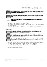
Page 148: ...9 2 HAKUBA 26PPM Laser Printer Base Engine Technical Manual Version 1 0 Adjustment Mode...

Page 149: ...Press the Select Button Media Size will be displayed Press Select You will have a choice of the following sizes for the tray 6 Use the Next Button to display your choice and press Select 7 Press the...

Page 150: ...turn until Test Print Default Source is displayed Use the Next Button to scroll down until Grid Page is displayed Press Select 5 A Grid Page will be printed Mark the page with the tray or feeder that...

Page 151: ...will move the image down the page Decreasing the value moves the image up For the scan direction increasing the value moves the image to the left and decreasing the value moves the image to the right...

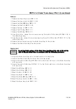
Page 152: ...9 6 HAKUBA 26PPM Laser Printer Base Engine Technical Manual Version 1 0 Adjustment Mode...

Page 153: ...P 1 1 7 Cover Right PL1 1 8 10 20 RRP 1 1 8 Cover Assy Front PL1 1 9 10 22 RRP 1 1 9 Tray Assy MBF PL1 1 17 10 24 RRP 1 1 10 Cover Front L H PL1 1 19 10 26 RRP 1 2 Covers 2 RRP 1 2 1 Cap Envelope PL1...

Page 154: ...MBF PL4 1 6 10 82 RRP 4 1 4 Tray Bottom Assy PL4 1 8 10 84 RRP 4 1 5 Actuator N P MBF PL4 1 12 10 86 RRP 4 1 6 Pad Assy Retard PL4 1 15 10 88 RRP 4 1 7 Sensor Photo Paper Set PL4 1 19 10 90 RRP 4 1 8...

Page 155: ...1 10 144 RRP 7 1 5 Sensor Photo Exit PL7 1 16 10 148 RRP 7 1 6 Cover Interlock PL7 1 18 10 150 RRP 7 1 7 Motor Assy Exit PL7 1 21 10 152 RRP 7 1 8 Chute Assy Exit with 1 17 19 24 Reference Only 10 154...

Page 156: ...1 2 Harness Assy OCT M PL10 1 4 10 184 RRP 10 1 3 Switch Assy I L Rear PL10 1 7 10 186 RRP 10 1 4 Harness Assy DUP M PL10 1 9 10 188 RRP 10 1 5 PWBA CONN PL10 1 11 10 192 RRP 10 1 6 Switch Assy I L F...

Page 157: ...work for the FUSER ASSY periphery wait until the FUSER ASSY and its periphery have become cool enough 7 Disconnect all interface cables from the rear panel of printer 8 In performing work to eliminat...

Page 158: ...sponds to the plate PL g X Yh item g Zh in Section 12 Parts List Therefore the shape and mounting position of the parts can be confirmed in Section 12 Parts List g PPR X Y Z h in the text or at the en...

Page 159: ...UBA 26PPM Laser Printer Base Engine Technical Manual 10 7 Version 1 0 Removal and Replacement Procedures RRPs Section 10 Removal and Replacement Procedures RRPs continued This Page is Intentionally Bl...

Page 160: ...10 8 HAKUBA 26PPM Laser Printer Base Engine Technical Manual Version 1 0 Removal and Replacement Procedures RRPs RRP 1 1 1 Cover Left PL1 1 1 Figure 2 Cover Left Removal...

Page 161: ...ve the two screws securing the Cover Left to the printer 3 Remove the Cover Left from the printer Replacement In the following steps mount the Cover Left while paying attention to the sections overlap...

Page 162: ...10 10 HAKUBA 26PPM Laser Printer Base Engine Technical Manual Version 1 0 Removal and Replacement Procedures RRPs RRP 1 1 2 Cover Assy I F PL1 1 2 Figure 3 Cover Assy I F Removal...

Page 163: ...two screws securing the Cover Assy I F to the printer 2 Remove the Cover Assy I F from the printer Replacement In the following steps mount the Cover Assy I F while paying attention to the sections o...

Page 164: ...10 12 HAKUBA 26PPM Laser Printer Base Engine Technical Manual Version 1 0 Removal and Replacement Procedures RRPs RRP 1 1 3 Cover Option PL1 1 4 Figure 4 Cover Option Removal...

Page 165: ...hing two latches at the rear of Cover Option from the printer release the latches from the Cover Assy Top PL1 1 5 3 Remove the Cover Option from the printer Replacement 1 Align four bosses at the fron...

Page 166: ...10 14 HAKUBA 26PPM Laser Printer Base Engine Technical Manual Version 1 0 Removal and Replacement Procedures RRPs RRP 1 1 4 Cover Assy Top PL1 1 5 Figure 5 Cover Assy Top Removal...

Page 167: ...Panel PL1 1 6 7 Remove the Cover Assy Top from the printer 8 Remove the Control Assy Panel RRP 1 1 5 Replacement In the following steps mount the Cover Assy Top while paying attention to the sections...

Page 168: ...10 16 HAKUBA 26PPM Laser Printer Base Engine Technical Manual Version 1 0 Removal and Replacement Procedures RRPs RRP 1 1 5 Control Assy panel PL1 1 6 Figure 6 Control Assy Panel Removal...

Page 169: ...the Control Assy Panel to the Cover Assy Top PL1 1 5 6 Remove the Control Assy Panel from the Cover Assy Top Replacement In the following steps mount the Control Assy Panel while paying attention to...

Page 170: ...10 18 HAKUBA 26PPM Laser Printer Base Engine Technical Manual Version 1 0 Removal and Replacement Procedures RRPs RRP 1 1 6 Harness Assy Panel PL1 1 7 Figure 7 Harness Assy Panel Removal...

Page 171: ...nplug the connector P J363 of Harness Assy Panel from the Control Assy Panel PL1 1 6 and remove the Harness Assy Panel Replacement In the following steps mount the Harness Assy Panel while paying atte...

Page 172: ...10 20 HAKUBA 26PPM Laser Printer Base Engine Technical Manual Version 1 0 Removal and Replacement Procedures RRPs RRP 1 1 7 Cover Right PL1 1 8 Figure 8 Cover Right Removal...

Page 173: ...Right from the holes in the printer 7 Disengage two hooks at the bottom of Cover Right from the holes in the printer 8 Remove the Cover Right Replacement In the following steps mount the Cover Right...

Page 174: ...10 22 HAKUBA 26PPM Laser Printer Base Engine Technical Manual Version 1 0 Removal and Replacement Procedures RRPs RRP 1 1 8 Cover Assy Front PL1 1 9 Figure 9 Cover Assy Front Removal...

Page 175: ...res the Cover Assy Front to the printer 6 Sliding the Cover Assy Front to the right from the printer release the left and right bearing bores of Cover Assy Front from the left and right studs then rem...

Page 176: ...10 24 HAKUBA 26PPM Laser Printer Base Engine Technical Manual Version 1 0 Removal and Replacement Procedures RRPs RRP 1 1 9 Tray Assy MBF PL1 1 17 Figure 10 Tray Assy MBF Removal...

Page 177: ...Front and Tray Assy MBF to deflect the left side of Cover Assy Front and disengage the boss then detach the Tray Assy MBF 6 Aligning the boss of Tray Assy MBF with a slit of Stopper Tray remove the Tr...

Page 178: ...10 26 HAKUBA 26PPM Laser Printer Base Engine Technical Manual Version 1 0 Removal and Replacement Procedures RRPs RRP 1 1 10 Cover Front L H PL1 1 19 Figure 11 Cover Front L H Removal...

Page 179: ...Cover L H draw it a little toward the front from the printer 4 Remove the Cover L H from the printer Replacement In the following steps mount the Cover L H while paying attention to the sections over...

Page 180: ...10 28 HAKUBA 26PPM Laser Printer Base Engine Technical Manual Version 1 0 Removal and Replacement Procedures RRPs RRP 1 2 1 Cap Envelope PL1 2 7 Figure 12 Cap Envelope Removal...

Page 181: ...aw the right Cap Envelope secured to the Chute Assy Face Up PL1 2 8 from the Cover Assy Rear 3 Draw the left Cap Envelope secured to the Chute Assy Face Up from the Cover Assy Rear Replacement 1 Mount...

Page 182: ...10 30 HAKUBA 26PPM Laser Printer Base Engine Technical Manual Version 1 0 Removal and Replacement Procedures RRPs RRP 1 2 2 Stopper PL1 2 10 Figure 13 Stopper Removal...

Page 183: ...topper PL1 2 10 continued Removal 1 Remove the Cover Assy Rear RRP1 2 3 2 Remove the one screw securing the Stopper to the printer 3 Remove the Stopper to the printer Replacement 1 Align the Stopper w...

Page 184: ...32 HAKUBA 26PPM Laser Printer Base Engine Technical Manual Version 1 0 Removal and Replacement Procedures RRPs RRP 1 2 3 Cover Assy Rear Standard Reference Only Figure 14 Cover Assy Rear Standard Remo...

Page 185: ...the left Cover Assy Rear to the printer 4 Sliding the Cover Assy Rear to the left release the bearing bores of Cover Assy Rear from the left and right bosses of printer and remove it from the printer...

Page 186: ...10 34 HAKUBA 26PPM Laser Printer Base Engine Technical Manual Version 1 0 Removal and Replacement Procedures RRPs RRP 1 2 4 Chute Assy Face Up PL1 2 8 Figure 15 Chute Assy Face Up Removal...

Page 187: ...the two screws securing the Chute Assy Face Up to the Cover Assy Rear 3 Remove the Chute Assy Face Up from the Cover Assy Rear Replacement 1 Engage the right hole in the Chute Assy Face Up with a bos...

Page 188: ...10 36 HAKUBA 26PPM Laser Printer Base Engine Technical Manual Version 1 0 Removal and Replacement Procedures RRPs RRP 2 1 1 Cassette Assy PL2 1 1 Figure 16 Cassette Assy Removal...

Page 189: ...al Manual 10 37 Version 1 0 Removal and Replacement Procedures RRPs RRP 2 1 1 Cassette Assy PL2 1 1 continued Removal 1 Draw the Cassette Assy from the printer Replacement 1 Aligning the position exac...

Page 190: ...26PPM Laser Printer Base Engine Technical Manual Version 1 0 Removal and Replacement Procedures RRPs RRP 2 2 1 Clutch Assy Friction PL2 2 7 Figure 17 Clutch Assy Friction Removal 1 Figure 18 Clutch As...

Page 191: ...he Cassette Assy 4 Remove the Roll Assy RRP 2 2 2 5 Draw the Clutch Assy Friction of the shaft of Shaft Assy Retard PL2 2 6 from the Cassette Assy Replacement 1 Align the position of Clutch Assy Frict...

Page 192: ...0 40 HAKUBA 26PPM Laser Printer Base Engine Technical Manual Version 1 0 Removal and Replacement Procedures RRPs RRP 2 2 2 Roll Assy PL2 2 8 Figure 19 Roll Assy Removal 1 Figure 20 Roll Assy Removal 2...

Page 193: ...tard Base R from the Cassette Assy 4 Unhook the Roll Assy secured to the groove of Shaft Assy Retard PL2 2 6 from the Cassette Assy 5 Draw the Roll Assy from Shaft Assy Retard Replacement 1 Aligning t...

Page 194: ...10 42 HAKUBA 26PPM Laser Printer Base Engine Technical Manual Version 1 0 Removal and Replacement Procedures RRPs RRP 2 2 3 Spring Retard PL2 2 10 Figure 21 Spring Retard 1 Figure 22 Spring Retard 2...

Page 195: ...ard Base R from the Cassette Assy 4 Open the Bracket Retard PL2 2 9 from the Cassette Assy 5 Remove the Spring Retard from the Cassette Assy Replacement 1 Align the Spring Retard with the specified mo...

Page 196: ...44 HAKUBA 26PPM Laser Printer Base Engine Technical Manual Version 1 0 Removal and Replacement Procedures RRPs RRP 2 2 4 Motor Assy PL2 2 22 Figure 23 Motor Assy Removal 1 Figure 24 Motor Assy Removal...

Page 197: ...7 Remove the three screws securing the Motor Assy to the Cassette Assy 8 Remove the Motor Assy from the Cassette Assy Replacement 1 Engaging the groove at a rotational part of Motor Assy with the boss...

Page 198: ...ter Base Engine Technical Manual Version 1 0 Removal and Replacement Procedures RRPs RRP 2 2 5 Connector PL2 2 25 and Guide Socket PL2 2 27 Figure 25 Connector and Guide Socket Removal 1 Figure 26 Con...

Page 199: ...he Guide Socket together with Connector from the Cassette Assy 7 Remove the Spring RRP 2 2 26 8 Sliding the Connector upward disconnect it from the Guide Socket Replacement 1 Aligning the Connector wi...

Page 200: ...10 48 HAKUBA 26PPM Laser Printer Base Engine Technical Manual Version 1 0 Removal and Replacement Procedures RRPs RRP 2 2 6 Spring PL2 2 26 Figure 27 Spring Removal 1 Figure 28 Spring Removal 2...

Page 201: ...ette Assy In the following steps take care not to drop and miss the Spring PL2 2 26 4 Remove the Guide Socket RRP 2 2 5 5 Remove the Spring from the Cassette Assy Replacement In the following steps ta...

Page 202: ...KUBA 26PPM Laser Printer Base Engine Technical Manual Version 1 0 Removal and Replacement Procedures RRPs RRP 3 1 1 Roll Assy Turn PL3 1 1 Figure 29 Roll Assy Turn Removal 1 Figure 30 Roll Assy Turn R...

Page 203: ...the Plate Assy Left RRP 9 1 1 9 Remove the Plate Handle RRP 9 1 3 10 Remove the PWBA HKB PS RRP 10 1 9 11 Remove the Feeder RRP 3 1 10 12 Unplug the connector P J641 on the Clutch Assy Turn PL3 1 2 f...

Page 204: ...he Spring Chute RRP 3 1 2 4 Align the Roll Assy Turn together with the Spring Extension and Spring Chute to the Feeder 5 Secure the Roll Assy Turn to the Feeder with four screws 6 Plug the connector P...

Page 205: ...HAKUBA 26PPM Laser Printer Base Engine Technical Manual 10 53 Version 1 0 Removal and Replacement Procedures RRPs RRP 3 1 1 Roll Assy Turn PL3 1 1 continued Blank Page...

Page 206: ...10 54 HAKUBA 26PPM Laser Printer Base Engine Technical Manual Version 1 0 Removal and Replacement Procedures RRPs RRP 3 1 2 Spring Chute PL3 1 4 Figure 31 Spring Chute Removal...

Page 207: ...1 3 and Spring Chute PL3 1 4 from the Feeder 15 Unhook the Spring Chute securing to the Roll Assy Turn at two places and remove the Spring Chute Replacement 1 Hook the Spring Chute to the boss of the...

Page 208: ...10 56 HAKUBA 26PPM Laser Printer Base Engine Technical Manual Version 1 0 Removal and Replacement Procedures RRPs RRP 3 1 3 Actuator N P PL3 1 6 Figure 32 Actuator N P Removal...

Page 209: ...RRP 3 1 10 12 Unhook the left and right shafts of Actuator N P from the left and right Support Actuators PL3 1 7 and remove the Actuator N P from the Feeder Replacement 1 Aligning the position exactl...

Page 210: ...UBA 26PPM Laser Printer Base Engine Technical Manual Version 1 0 Removal and Replacement Procedures RRPs RRP 3 1 4 Sensor Photo Face Control Low Paper PL3 1 13 Figure 33 Sensor Photo Face Control Pape...

Page 211: ...ace Control 14 Unplug the connector P J661 on the right Sensor Photo Low Paper from the Feeder 15 Disengage five hooks of right Sensor Photo Low Paper from the Feeder and remove the Sensor Photo Low P...

Page 212: ...26PPM Laser Printer Base Engine Technical Manual Version 1 0 Removal and Replacement Procedures RRPs RRP 3 1 5 Feeder Assy PL3 1 19 Figure 34 Feeder Assy Removal 1 Figure 35 Feeder Assy Removal 2 eng...

Page 213: ...e the Feeder RRP 3 1 10 12 Remove the Clutch Assy Feed RRP 3 1 8 13 Remove the Sensor Photo Face Control RRP 3 1 4 14 Disengage the E ring that secures the left shaft of Feeder Assy to the Feeder In t...

Page 214: ...left bearing bore of Feeder and slide the Feeder Assy to the left 3 Secure the left shaft of Feeder Assy to the Feeder with the Bearing PL3 1 38 4 Restore the reversed Feeder so that the top surface...

Page 215: ...HAKUBA 26PPM Laser Printer Base Engine Technical Manual 10 63 Version 1 0 Removal and Replacement Procedures RRPs RRP 3 1 5 Feeder Assy PL3 1 19 continued Blank Page...

Page 216: ...10 64 HAKUBA 26PPM Laser Printer Base Engine Technical Manual Version 1 0 Removal and Replacement Procedures RRPs RRP 3 1 6 Roll Assy PL3 1 26 Figure 36 Roll Assy Removal...

Page 217: ...e front shaft of Feeder Assy 4 Unhook the Roll Assy secured to the rear shaft of Feeder Assy from the Feeder 5 Draw the Roll Assy from the rear shaft of Feeder Assy Replacement 1 Insert the Roll Assy...

Page 218: ...10 66 HAKUBA 26PPM Laser Printer Base Engine Technical Manual Version 1 0 Removal and Replacement Procedures RRPs RRP 3 1 7 PWBA Feeder PL3 1 36 Figure 37 PWBA Feeder Removal...

Page 219: ...ver Assy Top RRP 1 1 4 7 Remove the Cover Right RRP 1 1 7 8 Remove the Plate Assy Left RRP 9 1 1 9 Remove the Plate Handle RRP 9 1 3 10 Remove the PWBA HKB PS RRP 10 1 9 11 Remove the Feeder RRP 3 1 1...

Page 220: ...ug the connector P J65 to the PWBA Feeder 5 Plug the connector P J66 to the PWBA Feeder 6 Plug the connector P J67 to the PWBA Feeder 7 Mount the Feeder RRP 3 1 10 8 Mount the PWBA HKB PS RRP 10 1 9 9...

Page 221: ...HAKUBA 26PPM Laser Printer Base Engine Technical Manual 10 69 Version 1 0 Removal and Replacement Procedures RRPs RRP 3 1 7 PWBA Feeder PL3 1 36 continued Blank page...

Page 222: ...26PPM Laser Printer Base Engine Technical Manual Version 1 0 Removal and Replacement Procedures RRPs RRP 3 1 8 Clutch Assy Feed PL3 1 37 Figure 38 Clutch Assy Feed Removal 1 Figure 39 Clutch Assy Fee...

Page 223: ...9 1 1 9 Remove the Plate Handle RRP 9 1 3 10 Remove the PWBA HKB PS RRP 10 1 9 11 Remove the Feeder RRP 3 1 10 12 Remove a screw fixing Cramp PL 3 1 44 and Bracket PL 3 1 33 from the Feeder 13 Remove...

Page 224: ...r 2 PL3 1 31 into the shaft of Feeder 6 Aligning the position exactly insert the Gear 3 PL3 1 34 into the shaft of Feeder 7 Align the Bracket PL3 1 33 with its mount position to the Feeder 8 Tighten t...

Page 225: ...HAKUBA 26PPM Laser Printer Base Engine Technical Manual 10 73 Version 1 0 Removal and Replacement Procedures RRPs RRP 3 1 8 Clutch Assy Feed PL3 1 37 continued Blank page...

Page 226: ...10 74 HAKUBA 26PPM Laser Printer Base Engine Technical Manual Version 1 0 Removal and Replacement Procedures RRPs RRP 3 1 9 Socket PL3 1 40 Figure 40 Socket Removal...

Page 227: ...g steps do not detach Feeder and Socket far away because they are connected with the harness 3 Detach the Socket a little from the Feeder 4 Unplug the connector P J671 from the Socket Replacement 1 Pl...

Page 228: ...10 76 HAKUBA 26PPM Laser Printer Base Engine Technical Manual Version 1 0 Removal and Replacement Procedures RRPs RRP 3 1 10 Feeder with1 40 Reference Only Figure 41 Feeder Removal...

Page 229: ...he Plate Handle RRP 9 1 3 10 Remove the PWBA HKB PS RRP 10 1 9 11 Remove the seven screws securing the Feeder to the Printer 12 Draw the Feeder toward the front to remove from the printer Replacement...

Page 230: ...10 78 HAKUBA 26PPM Laser Printer Base Engine Technical Manual Version 1 0 Removal and Replacement Procedures RRPs RRP 4 1 1 Chute MBF Assy PL4 1 1 Figure 42 Chute MBF Assy Removal...

Page 231: ...ee clamps securing the harness of Chute MBF Assy to the printer 7 Remove the four screws securing the Chute MBF Assy to the Printer 8 Remove the Chute MBF Assy from the printer Replacement 1 Align the...

Page 232: ...26PPM Laser Printer Base Engine Technical Manual Version 1 0 Removal and Replacement Procedures RRPs RRP 4 1 2 Roll Assy MBF with 3 6 28 PL4 1 2 Figure 43 Roll Assy MBF Removal 1 Figure 44 Roll Assy M...

Page 233: ...9 Raising the right shaft of Roll Assy MBF with 3 6 28 draw off the Roll Assy MBF with 3 6 28 toward the diagonal right while passing the boss of left shaft of Shaft Assy MBF through the left slit of...

Page 234: ...10 82 HAKUBA 26PPM Laser Printer Base Engine Technical Manual Version 1 0 Removal and Replacement Procedures RRPs RRP 4 1 3 Roll Assy MBF PL4 1 6 Figure 45 Roll Assy MBF Removal...

Page 235: ...to the right which is secured to the Shaft Assy MBF and raise it upward to remove from the Chute MBF Assy Replacement 1 Aligning the position exactly mount the Roll Assy MBF on the shaft of Shaft Assy...

Page 236: ...A 26PPM Laser Printer Base Engine Technical Manual Version 1 0 Removal and Replacement Procedures RRPs RRP 4 1 4 Tray Bottom Assy PL4 1 8 Figure 46 Tray Bottom Assy Removal 1 Figure 47 Tray Bottom Ass...

Page 237: ...s of Tray Bottom Assy Replacement 1 Mount the Bearing Exits on the left and right shafts of Tray Bottom Assy 2 Aligning the position exactly mount the Tray Bottom Assy together with the left and right...

Page 238: ...26PPM Laser Printer Base Engine Technical Manual Version 1 0 Removal and Replacement Procedures RRPs RRP 4 1 5 Actuator N P MBF PL4 1 12 Figure 48 Actuator N P MBF Removal 1 Figure 49 Actuator N P MB...

Page 239: ...the Chute MBF Assy Replacement 1 Aligning the position exactly mount the Actuator N P MBF on the back of Tray Bottom PL4 1 11 in the Chute MBF Assy PL4 1 1 2 Secure the shaft of Actuator N P MBF to t...

Page 240: ...BA 26PPM Laser Printer Base Engine Technical Manual Version 1 0 Removal and Replacement Procedures RRPs RRP 4 1 6 Pad Assy Retard PL4 1 15 Figure 50 Pad Assy Retard Removal 1 Figure 51 Pad Assy Retard...

Page 241: ...ole in the Pad Assy Retard from the boss of Chute MBF Assy and remove the Pad Assy Retard Replacement 1 Engage the hole in the right bracket of Pad Assy Retard with the right boss of Chute MBF Assy PL...

Page 242: ...ser Printer Base Engine Technical Manual Version 1 0 Removal and Replacement Procedures RRPs RRP 4 1 7 Sensor Photo Paper Set PL4 1 19 Figure 52 Sensor Photo Paper Set Removal 1 Figure 53 Sensor Photo...

Page 243: ...and remove the Sensor Photo Paper Set from the Chute Assy MBF Replacement 1 Aligning the position exactly secure the Sensor Photo Paper Set to the Chute Assy MBF with five hooks 2 Plug the connector P...

Page 244: ...10 92 HAKUBA 26PPM Laser Printer Base Engine Technical Manual Version 1 0 Removal and Replacement Procedures RRPs RRP 4 1 8 Solenoid Pick Up PL4 1 23 Figure 54 Solenoid Pick Up Removal...

Page 245: ...P 4 1 9 5 Remove the Gear Pick Up RRP 4 1 10 6 Remove the one screw securing the Solenoid Pick Up to the Chute MBF Assy 7 Remove the Solenoid Pick Up from the Chute MBF Assy Replacement 1 Align the So...

Page 246: ...10 94 HAKUBA 26PPM Laser Printer Base Engine Technical Manual Version 1 0 Removal and Replacement Procedures RRPs RRP 4 1 9 Spring MBF PL4 1 24 Figure 55 Spring MBF Removal...

Page 247: ...hute MBF Assy RRP 4 1 1 4 Unhook the Spring MBF secured to the Gear Pick Up PL4 1 25 from the Chute MBF Assy PL4 1 1 5 Unhook the Spring MBF secured to the hole in the Chute MBF Assy and remove the Sp...

Page 248: ...10 96 HAKUBA 26PPM Laser Printer Base Engine Technical Manual Version 1 0 Removal and Replacement Procedures RRPs RRP 4 1 10 Gear Pick Up PL4 1 25 Figure 56 Gear Pick Up Removal engine rrp051FA...

Page 249: ...g MBF RRP 4 1 9 5 Unhook the Gear Pick Up secured to the Shaft Assy MBF PL4 1 3 from the Chute MBF Assy PL4 1 1 6 Draw the Gear Pick Up from the Shaft Assy MBF Replacement 1 Insert the Gear Pick Up in...

Page 250: ...10 98 HAKUBA 26PPM Laser Printer Base Engine Technical Manual Version 1 0 Removal and Replacement Procedures RRPs RRP 4 1 11 Connector Assy ENV PL4 1 27 Figure 57 Connector Assy ENV Removal...

Page 251: ...remove it from the Chute Assy MBF PL4 1 1 5 Remove the one screw securing the Connector Assy ENV to the Plate ENV Assy 6 Remove the Connector Assy ENV from the Plate ENV Assy Replacement 1 Align the...

Page 252: ...10 100 HAKUBA 26PPM Laser Printer Base Engine Technical Manual Version 1 0 Removal and Replacement Procedures RRPs RRP 4 1 12 Tray Bottom Pick Up with9 10 Reference Only Figure 58 Tray Pick Up Removal...

Page 253: ...the shaft of Tray Bottom Assy Replacement 1 Aligning the position exactly mount the Tray Bottom Pick Up on the shaft of Tray Bottom Assy PL4 1 14 from the Chute MBF Assy PL4 1 1 2 Rotate the Tray Bot...

Page 254: ...10 102 HAKUBA 26PPM Laser Printer Base Engine Technical Manual Version 1 0 Removal and Replacement Procedures RRPs RRP 5 1 1 P H Assy PL5 1 4 Figure 59 P H Assy Removal 1 Figure 60 P H Assy Removal 2...

Page 255: ...he harness of P H Assy 9 Remove the five screws securing the P H Assy to the printer 10 Raising a little the right end of P H Assy to shift to the right remove the P H Assy upward from the printer Rep...

Page 256: ...inter Base Engine Technical Manual Version 1 0 Removal and Replacement Procedures RRPs RRP 5 1 2 Roll Regi Rubber PL5 1 7 Figure 61 Roll Regi Rubber Removal 1 Figure 62 Roll regi Rubber Removal 2 engi...

Page 257: ...g Metal R PL5 1 31 14 Closing the Chute Upper Assy and Chute Inlet PL5 1 8 align the boss of Bearing Metal R with the right slit and draw the Bearing Metal R from the P H Assy 15 Closing the Chute Upp...

Page 258: ...losing the Chute Upper Assy and Chute Inlet from the P H Assy engage the boss of Bearing Metal PL5 1 13 with the left slit and secure the Roll Regi Metal with the Bearing Metal 9 Closing the Chute Upp...

Page 259: ...HAKUBA 26PPM Laser Printer Base Engine Technical Manual 10 107 Version 1 0 Removal and Replacement Procedures RRPs RRP 5 1 2 Roll Regi Rubber PL5 1 7 continued Blank Page...

Page 260: ...10 108 HAKUBA 26PPM Laser Printer Base Engine Technical Manual Version 1 0 Removal and Replacement Procedures RRPs RRP 5 1 3 Actuator Regi PL5 1 10 Figure 63 Actuator Regi Removal...

Page 261: ...e the Spring Sensor Regi inserted in the shaft of Actuator Regi Replacement 1 Insert the Spring Sensor Regi PL5 1 11 into the right shaft of Actuator Regi 2 Holding the operating lever of Actuator Reg...

Page 262: ...10 110 HAKUBA 26PPM Laser Printer Base Engine Technical Manual Version 1 0 Removal and Replacement Procedures RRPs RRP 5 1 4 Spring Sensor Regi PL5 1 11 Figure 64 Spring Sensor Regi Removal...

Page 263: ...ove the Spring Sensor Regi inserted in the shaft of Actuator Regi Replacement 1 Insert the Spring Sensor Regi into the right shaft of Actuator Regi PL5 1 10 2 Holding the operating lever of Actuator R...

Page 264: ...10 112 HAKUBA 26PPM Laser Printer Base Engine Technical Manual Version 1 0 Removal and Replacement Procedures RRPs RRP 5 1 5 Sensor Photo Regi PL5 1 12 Figure 65 Sensor Photo Regi Removal...

Page 265: ...the Actuator Regi RRP 5 1 4 9 Unplug the connector P J432 from the Sensor Photo 10 Disengage three hooks that secure the Sensor Photo and remove the Sensor Photo from the rear side of P H Assy Replac...

Page 266: ...10 114 HAKUBA 26PPM Laser Printer Base Engine Technical Manual Version 1 0 Removal and Replacement Procedures RRPs RRP 5 1 6 Spring Regi L PL5 1 14 Figure 66 Spring Regi L Removal...

Page 267: ...egi L from the P H Assy PL5 1 4 12 Draw downward the left Spring Regi L from the P H Assy Replacement 1 From the left side of P H Assy PL5 1 4 pass the hook at the top of Spring Regi L through a secti...

Page 268: ...10 116 HAKUBA 26PPM Laser Printer Base Engine Technical Manual Version 1 0 Removal and Replacement Procedures RRPs RRP 5 1 7 Gear Regi Metal PL5 1 15 Figure 67 Gear Regi Metal Removal...

Page 269: ...10 6 Remove the P H Assy RRP 5 1 1 7 Disengage the E ring that secures the Gear Regi Metal from the P H Assy PL5 1 4 8 Draw the Gear Regi Metal from the P H Assy Replacement 1 Mount the Gear Regi Meta...

Page 270: ...10 118 HAKUBA 26PPM Laser Printer Base Engine Technical Manual Version 1 0 Removal and Replacement Procedures RRPs RRP 5 1 8 Gear Regi Rubber PL5 1 16 Figure 68 Gear regi Rubber Removal...

Page 271: ...6 Remove the P H Assy RRP 5 1 1 7 Disengage the E ring that secures the Gear Regi Rubber from the P H Assy PL5 1 4 8 Draw the Gear Regi Rubber from the P H Assy Replacement 1 Mount the Gear Regi Rubb...

Page 272: ...10 120 HAKUBA 26PPM Laser Printer Base Engine Technical Manual Version 1 0 Removal and Replacement Procedures RRPs RRP 5 1 9 Clutch Regi PL5 1 19 Figure 69 Clutch Regi Removal...

Page 273: ...g the connector P J433 of the Clutch Regi 8 Disengage the E ring that secures the Clutch Regi from the P H Assy PL5 1 4 9 Draw the Clutch Regi from the P H Assy Replacement 1 Mount the Clutch Regi on...

Page 274: ...PM Laser Printer Base Engine Technical Manual Version 1 0 Removal and Replacement Procedures RRPs RRP 5 1 10 Shaft 14 PL5 1 34 and Gear 14 PL5 1 35 Figure 70 Shaft 14 Removal Figure 71 Gear 14 Removal...

Page 275: ...ollowing steps take care not to drop and then damage the Gear 14 4 Holding the Gear 14 draw off the Shaft 14 that secures the P H Assy PL5 1 4 from the printer using long nose pliers 5 Remove the Gear...

Page 276: ...124 HAKUBA 26PPM Laser Printer Base Engine Technical Manual Version 1 0 Removal and Replacement Procedures RRPs RRP 5 1 11 Kit Toner Sensor with 1 2 33 Reference Only Figure 72 Kit Toner Sensor Remov...

Page 277: ...bracket of Chute Upper Assy PL5 1 6 9 Desengage the right boss of Kit Toner Sensor from the hole in the right bracket of Chute Upper Assy and remove the Kit Toner Sensor from the P H Assy Replacement...

Page 278: ...10 126 HAKUBA 26PPM Laser Printer Base Engine Technical Manual Version 1 0 Removal and Replacement Procedures RRPs RRP 6 1 1 BTR Assy PL6 1 2 Figure 73 BTR Assy Removal...

Page 279: ...at secure the BTR Assy from the printer 3 Holding the left and right knobs of BTR Assy remove the BTR Assy from the BTR Chute Assy Replacement In replacing the BTR Assy with a new one peel off the str...

Page 280: ...10 128 HAKUBA 26PPM Laser Printer Base Engine Technical Manual Version 1 0 Removal and Replacement Procedures RRPs RRP 6 1 2 Chute Trans Assy PL6 1 3 Figure 74 Chute Trans Assy Removal engine rrp069FA...

Page 281: ...o screws securing the Chute Trans Assy to the printer 11 Remove the Chute Trans Assy from the printer Replacement Do not bend both springs of the Chute Trans Assy placed the side of CR and the side of...

Page 282: ...10 130 HAKUBA 26PPM Laser Printer Base Engine Technical Manual Version 1 0 Removal and Replacement Procedures RRPs RRP 6 1 3 Fuser Assy PL6 1 7 Figure 75 Fuser Assy Removal...

Page 283: ...sy PL6 1 7 continued Removal 1 Open the Cover Assy Rear from the printer 2 Remove the two screws securing the Fuse Assy to the printer 3 Remove the Fuser Assy from the Printer Replacement 1 Align the...

Page 284: ...10 132 HAKUBA 26PPM Laser Printer Base Engine Technical Manual Version 1 0 Removal and Replacement Procedures RRPs RRP 6 1 4 Harness Assy Fuser M PL6 1 12 Figure 76 Harness Assy Fuser M Removal...

Page 285: ...e Plate Assy Left RRP 9 1 1 14 Remove the CRU Top Guide Assy RRP 8 1 1 15 Remove the Plate Handle RRP 9 1 3 16 Remove the PWBA HKB26 MCU RRP 10 1 7 17 Remove the Motor Assy Main RRP 8 1 4 18 Remove th...

Page 286: ...ther with PWBA HVPS to the printer with one screw 8 Plug the connector P J262 to the PWBA HVPS PL10 1 20 9 Mount the Gear Assy Drive RRP 8 1 3 10 Mount the PWBA HKB PS RRP 10 1 9 11 Mount the Motor As...

Page 287: ...HAKUBA 26PPM Laser Printer Base Engine Technical Manual 10 135 Version 1 0 Removal and Replacement Procedures RRPs RRP 6 1 4 Harness Assy Fuser M PL6 1 12 continued Blank Page...

Page 288: ...10 136 HAKUBA 26PPM Laser Printer Base Engine Technical Manual Version 1 0 Removal and Replacement Procedures RRPs RRP 7 1 1 Eliminator Assy Exit PL7 1 1 Figure 77 Eliminator Assy Exit Removal...

Page 289: ...y Exit from the left mounting position of the Chute Assy Exit remove it from the printer 6 Draw the right end of Eliminator Assy Exit from the right mounting position of the Chute Assy Exit Replacemen...

Page 290: ...10 138 HAKUBA 26PPM Laser Printer Base Engine Technical Manual Version 1 0 Removal and Replacement Procedures RRPs RRP 7 1 2 Actuator Full Stack PL7 1 2 Figure 78 Actuator Full Stack Removal...

Page 291: ...ft of Actuator Full Stack to remove from the left bearing of Chute Assy Exit in the printer 7 Draw the right shaft of Actuator Full Stack from the right bearing of Chute Assy Exit and remove the Actua...

Page 292: ...ter Base Engine Technical Manual Version 1 0 Removal and Replacement Procedures RRPs RRP 7 1 3 Bearing Exit PL7 1 6 Bearing MID PL7 1 25 and Roll Assy MID 1 PL7 1 7 Figure 79 Bearing Exit Bearing MID...

Page 293: ...gine Technical Manual 10 141 Version 1 0 Removal and Replacement Procedures RRPs RRP 7 1 3 Bearing Exit PL7 1 6 Bearing MID PL7 1 25 and Roll Assy MID 1 PL7 1 7 continued Figure 80 Bearing Exit Bearin...

Page 294: ...ook the Gear Exit 17 secured to the Roll Assy MID 2 PL7 1 11 from the Chute Assy Exit 14 Draw the Gear Exit 17 from the Roll Assy MID 2 15 Remove the Gear Exit 32 PL7 1 23 from the Chute Assy Exit 16...

Page 295: ...ssy MID 1 together with the left and right Bearing Exits on the Roll Assy MID 1 to the Chute Assy Exit 8 Secure the left and right shafts of upper Roll Assy MID 1 to the Chute Assy Exit with the hook...

Page 296: ...A 26PPM Laser Printer Base Engine Technical Manual Version 1 0 Removal and Replacement Procedures RRPs RRP 7 1 4 Bearing MID PL7 1 25 and Roll Assy MID 2 PL7 1 11 Figure 81 Bearing MID and Roll Assy M...

Page 297: ...inator Assy Exit RRP 7 1 1 10 Remove the Chute Assy Exit RRP 7 1 8 11 Unhook the Gear Exit 17 PL7 1 5 secured to the upper Roll Assy MID 1 PL7 1 7 from the Chute Assy Exit 12 Draw the Gear Exit 17 fro...

Page 298: ...ar Exit 32 PL7 1 23 into the Chute Assy Exit 5 Insert the Gear Exit 17 PL7 1 5 into the shaft of Roll Assy MID 2 from the Chute Assy Exit 6 Hook the Gear Exit 17 to the shaft of Roll Assy MID 2 7 Inse...

Page 299: ...HAKUBA 26PPM Laser Printer Base Engine Technical Manual 10 147 Version 1 0 Removal and Replacement Procedures RRPs RRP 7 1 4 Bearing Exit PL7 1 6 and Roll Assy MID 2 PL7 1 11 continued Blank Page...

Page 300: ...10 148 HAKUBA 26PPM Laser Printer Base Engine Technical Manual Version 1 0 Removal and Replacement Procedures RRPs RRP 7 1 5 Sensor Photo Exit PL7 1 16 Figure 82 Sensor Photo Exit Removal...

Page 301: ...on the Sensor Photo Exit 8 Disengage five hooks of Sensor Photo Exit secured to the Chute Assy Exit in the printer 9 Remove the Sensor Photo Exit from the Chute Assy Exit Replacement 1 Aligning the p...

Page 302: ...10 150 HAKUBA 26PPM Laser Printer Base Engine Technical Manual Version 1 0 Removal and Replacement Procedures RRPs RRP 7 1 6 Cover Interlock PL7 1 18 Figure 83 Cover Interlock Removal...

Page 303: ...ing the Stopper PL1 2 10 together with Cover Interlock to the printer 3 Remove the two screws securing the Cover interlock to the printer 4 Remove the Cover interlock from the printer Replacement 1 Al...

Page 304: ...10 152 HAKUBA 26PPM Laser Printer Base Engine Technical Manual Version 1 0 Removal and Replacement Procedures RRPs RRP 7 1 7 Motor Assy Exit PL7 1 21 Figure 84 Motor Assy Exit Removal...

Page 305: ...1 18 9 Remove the Chute Assy Exit RRP 7 1 8 10 Remove the two screw securing the Motor Assy Exit to the Chute Assy Exit 11 Remove the Motor Assy Exit from the Chute Assy Exit Replacement 1 Align the...

Page 306: ...ser Printer Base Engine Technical Manual Version 1 0 Removal and Replacement Procedures RRPs RRP 7 1 8 Chute Assy Exit with 1 17 19 24 Reference Only Figure 85 Chute Assy Exit Removal 1 Figure 86 Chut...

Page 307: ...KB26 MCU PL10 1 13 10 Unplug the connctor P J32 from the PWBA HKB26 MCU 11 Remove the three screw securing the Chute Assy Exit to the printer 12 Remove the Chute Assy Exit from the printer Replacement...

Page 308: ...10 156 HAKUBA 26PPM Laser Printer Base Engine Technical Manual Version 1 0 Removal and Replacement Procedures RRPs RRP 8 1 1 CRU Top Guide Assy PL8 1 4 Figure 87 CRU Top Guide Assy Removal...

Page 309: ...ew securing the CRU Top Guide Assy to the printer 10 Remove the CRU Top Guide Assy together with Sensor Assy CRU PL8 1 6 from the printer 11 Remove the Sensor Assy CRU RRP 8 1 5 Replacement 1 Mount th...

Page 310: ...10 158 HAKUBA 26PPM Laser Printer Base Engine Technical Manual Version 1 0 Removal and Replacement Procedures RRPs RRP 8 1 2 ROS Assy PL8 1 9 Figure 88 ROS Assy Removal...

Page 311: ...S Assy 8 Remove the four screws securing the ROS Assy to the printer 9 Raising the ROS Assy a little unplug the connector P J211 on the back side 10 Remove the ROS Assy from the printer Replacement 1...

Page 312: ...10 160 HAKUBA 26PPM Laser Printer Base Engine Technical Manual Version 1 0 Removal and Replacement Procedures RRPs RRP 8 1 3 Gear Assy Drive PL8 1 13 Figure 89 Gear Assy Drive Removal engine rrp084FA...

Page 313: ...y Top RRP 1 1 4 8 Remove the Cover Right RRP 1 1 7 9 Remove the Chute MBF Assy RRP 4 1 1 10 Remove the Shaft 14 RRP 5 1 10 11 Remove the Gear 14 RRP 5 1 10 12 Remove the P H Assy RRP 5 1 1 13 Remove t...

Page 314: ...er RRP 3 1 10 4 Mount the PWBA HKB PS RRP 10 1 9 5 Mount the Motor Assy Main RRP 8 1 4 6 Mount the PWBA HKB26 MCU RRP 10 1 7 7 Mount the Plate Handle RRP 9 1 3 8 Mount the CRU Top Guide Assy RRP 8 1 1...

Page 315: ...HAKUBA 26PPM Laser Printer Base Engine Technical Manual 10 163 Version 1 0 Removal and Replacement Procedures RRPs RRP 8 1 3 Gear Assy Drive PL8 1 13 continued Blank Page...

Page 316: ...10 164 HAKUBA 26PPM Laser Printer Base Engine Technical Manual Version 1 0 Removal and Replacement Procedures RRPs RRP 8 1 4 Motor Assy Main PL8 1 14 Figure 90 Motor Assy Main Removal...

Page 317: ...g steps take care not to drop and damage the Motor Assy Main 5 Remove the four screws securing the Motor Assy Main to the printer 6 Remove the Motor Assy Main from the printer Replacement In the follo...

Page 318: ...10 166 HAKUBA 26PPM Laser Printer Base Engine Technical Manual Version 1 0 Removal and Replacement Procedures RRPs RRP 8 1 5 Sensor Assy CRU with2 5 6 Reference Only Figure 91 Sensor Assy CRU Removal...

Page 319: ...h a small screwdriver draw off the right shaft of Sensor Assy CRU 11 Draw the left shaft of Sensor Assy CRU from the hole in the left bracket of CRU Top Guide Assy Replacement 1 Insert the left shaft...

Page 320: ...10 168 HAKUBA 26PPM Laser Printer Base Engine Technical Manual Version 1 0 Removal and Replacement Procedures RRPs RRP 9 1 1 Plate Assy Left PL9 1 1 Figure 92 Plate Assy Left Removal...

Page 321: ...Cover Assy I F RRP 1 1 2 4 Remove the Cover Left RRP 1 1 1 5 Remove the six screws securing the Plate Assy Left to the printer 6 Remove the Plate Assy Left from the printer Replacement 1 Align the Pl...

Page 322: ...10 170 HAKUBA 26PPM Laser Printer Base Engine Technical Manual Version 1 0 Removal and Replacement Procedures RRPs RRP 9 1 2 Fan Assy PL9 1 7 Figure 93 Fan Assy Removal...

Page 323: ...B26 MCU PL10 1 13 9 Release the harness of Fan Assy from two clamps from the printer 10 Remove the two screws securing the Fan Assy to the printer 11 Remove the Fan Assy from the printer Replacement 1...

Page 324: ...10 172 HAKUBA 26PPM Laser Printer Base Engine Technical Manual Version 1 0 Removal and Replacement Procedures RRPs RRP 9 1 3 Plate Handle PL9 1 12 Figure 94 Plate Handle Removal...

Page 325: ...the Cover Left RRP 1 1 1 5 Remove the Plate Assy Left RRP 9 1 1 6 Remove the four screws securing the Plate Handle to the printer 7 Remove the Plate Handle from the printer Replacement 1 Align the Pla...

Page 326: ...10 174 HAKUBA 26PPM Laser Printer Base Engine Technical Manual Version 1 0 Removal and Replacement Procedures RRPs RRP 9 1 4 PWBA Size 1 PL9 1 19 Figure 95 PWBA Size 1 Removal...

Page 327: ...the PWBA Size 1 far away because they are connected with the harness 10 Detach the PWBA Size 1 a little from the Housing Size Sensor 11 Unplug the connector P J331 from the PWBA Size 1 12 Unplug the c...

Page 328: ...10 176 HAKUBA 26PPM Laser Printer Base Engine Technical Manual Version 1 0 Removal and Replacement Procedures RRPs RRP 9 1 5 Harness Assy Size M PL9 1 20 Figure 96 Harness Assy Size M Removal...

Page 329: ...y Size M to the Housing Size Sensor PL9 1 21 11 Draw off the harness of Harness Assy Size M from three holes in the Housing Size Sensor and Remove the Harness Assy Size M Replacement 1 Insert the harn...

Page 330: ...78 HAKUBA 26PPM Laser Printer Base Engine Technical Manual Version 1 0 Removal and Replacement Procedures RRPs RRP 9 1 6 Size Sensor Housing with 14 18 Reference Only Figure 97 Size Sensor Housing Rem...

Page 331: ...ge two hooks of Size Sensor Housing from the Housing Assy Size Sensor 10 Remove the Size Sensor Housing from the Housing Assy Size Sensor Replacement 1 Disengage the back of Cam SW PL9 1 15 on Size Se...

Page 332: ...KUBA 26PPM Laser Printer Base Engine Technical Manual Version 1 0 Removal and Replacement Procedures RRPs RRP 9 1 7 Housing Assy Size Sensor with13 21 Reference Only Figure 98 Housing Assy Size Sensor...

Page 333: ...ing a boss that secures the Housing Assy Size Sensor to the printer with a small screwdriver draw off the Housing Assy Size Sensor toward the rear 10 Draw the harness of Housing Assy Size Sensor from...

Page 334: ...10 182 HAKUBA 26PPM Laser Printer Base Engine Technical Manual Version 1 0 Removal and Replacement Procedures RRPs RRP 10 1 1 PWB ESS PL10 1 2 Figure 99 PWB ESS Removal...

Page 335: ...uring the PWB ESS to the printer 5 Shifting the PWB ESS toward the rear unplug the connector from the printer 6 Remove the PWB ESS from the printer Replacement 1 Align the PWB ESS with its mount posit...

Page 336: ...10 184 HAKUBA 26PPM Laser Printer Base Engine Technical Manual Version 1 0 Removal and Replacement Procedures RRPs RRP 10 1 2 Harness Assy OCT M PL10 1 4 Figure 100 Harness Assy OCT M Removal...

Page 337: ...cause they are connected with the harness 10 Remove the two screws securing the Harness Assy OCT M to the printer 11 Detach the harness of Harness Assy OCT M a little from the printer 12 Draw the harn...

Page 338: ...10 186 HAKUBA 26PPM Laser Printer Base Engine Technical Manual Version 1 0 Removal and Replacement Procedures RRPs RRP 10 1 3 Switch Assy I L Rear PL10 1 7 Figure 101 Switch Assy I L Rear Removal...

Page 339: ...ause they are connected with the harness 12 Remove the two screws securing the Switch Assy I L Rear to the printer 13 Detach the harness of Harness Assy OCT M a little from the printer 14 Draw the har...

Page 340: ...10 188 HAKUBA 26PPM Laser Printer Base Engine Technical Manual Version 1 0 Removal and Replacement Procedures RRPs RRP 10 1 4 Harness Assy DUP M PL10 1 9 Figure 102 harness Assy DUP M Removal...

Page 341: ...the P H Assy RRP 5 1 1 12 Remove the Chute Trans Assy RRP 6 1 2 13 Remove the Plate Assy Left RRP 9 1 1 14 Remove the CRU Top Guide Assy RRP 8 1 1 15 Remove the Plate Handle RRP 9 1 3 16 Remove the P...

Page 342: ...P 8 1 3 6 Mount the PWBA LVES RRP 10 1 9 7 Mount the Motor Assy Main RRP 8 1 4 8 Mount the PWBA HKB26 MCU RRP 10 1 7 9 Mount the Plate Handle RRP 9 1 3 10 Mount the CRU Top Guide Assy RRP 8 1 1 11 Mou...

Page 343: ...HAKUBA 26PPM Laser Printer Base Engine Technical Manual 10 191 Version 1 0 Removal and Replacement Procedures RRPs RRP 10 1 4 Harness Assy DUP M PL10 1 9 continued Blank Page...

Page 344: ...10 192 HAKUBA 26PPM Laser Printer Base Engine Technical Manual Version 1 0 Removal and Replacement Procedures RRPs RRP 10 1 5 PWBA CONN PL10 1 11 Figure 103 PWBA CONN Removal...

Page 345: ...tor P J45 from the PWBA CONN 12 Unplug the connector P J231 from the PWBA CONN 13 Remove the three screws securing the PWBA CONN to the printer 14 Remove the PWBA CONN from the printer Replacement 1 A...

Page 346: ...10 194 HAKUBA 26PPM Laser Printer Base Engine Technical Manual Version 1 0 Removal and Replacement Procedures RRPs RRP 10 1 6 Switch Assy I L Front PL10 1 12 Figure 104 Switch Assy I L Front Removal...

Page 347: ...p the harness of Switch Assy I L Front from the printer 9 Remove the two screws securing the Switch Assy I L Front to the printer 10 Remove the Switch Assy I L Front from the printer Replacement 1 Ali...

Page 348: ...10 196 HAKUBA 26PPM Laser Printer Base Engine Technical Manual Version 1 0 Removal and Replacement Procedures RRPs RRP 10 1 7 PWBA HKB26 MCU PL10 1 13 Figure 105 PWBA HKB26 MCU Removal...

Page 349: ...Unplug the connector P J30 from the PWBA HKB26 MCU 11 Unplug the connector P J28 from the PWBA HKB26 MCU 12 Unplug the connector P J33 from the PWBA HKB26 MCU 13 Unplug the connector P J27 from the PW...

Page 350: ...B26 MCU 8 Plug the connector P J33 in the PWBA HKB26 MCU 9 Plug the connector P J27 in the PWBA HKB26 MCU 10 Plug the connector P J26 in the PWBA HKB26 MCU 11 Plug the connector P J22 in the PWBA HKB2...

Page 351: ...HAKUBA 26PPM Laser Printer Base Engine Technical Manual 10 199 Version 1 0 Removal and Replacement Procedures RRPs RRP 10 1 7 PWBA HKB26 MCU PL10 1 13 continued Blank Page...

Page 352: ...10 200 HAKUBA 26PPM Laser Printer Base Engine Technical Manual Version 1 0 Removal and Replacement Procedures RRPs RRP 10 1 8 PWBA HKB 5VDC PL10 1 14 Figure 106 PWBA HKB 5VDC Removal...

Page 353: ...PWBA HKB 5VDC 8 Unplug the connector P J101 from the PWBA HKB 5VDC 9 Remove the two screws securing the PWBA HKB 5VDC to the printer 10 Remove the PWBA HKB 5VDC from the printer Replacement 1 Align t...

Page 354: ...10 202 HAKUBA 26PPM Laser Printer Base Engine Technical Manual Version 1 0 Removal and Replacement Procedures RRPs RRP 10 1 9 PWBA HKB PS PL10 1 17 Figure 107 PWBA HKB PS Removal...

Page 355: ...lug the connector P J11 from the PWBA HKB PS 9 Unplug the connector P J285 from the PWBA HKB PS 10 Unplug the connector P J283 from the PWBA HKB PS 11 Unplug the connector P J281 from the PWBA HKB PS...

Page 356: ...th four screws 4 Plug the connector P J11 in the PWBA HKB PS 5 Plug the connector P J285 in the PWBA HKB PS 6 Plug the connector P J283 in the PWBA HKB PS 7 Plug the connector P J281 in the PWBA HKB P...

Page 357: ...HAKUBA 26PPM Laser Printer Base Engine Technical Manual 10 205 Version 1 0 Removal and Replacement Procedures RRPs RRP 10 1 9 PWBA HKB PS PL10 1 17 continued Blank Page...

Page 358: ...10 206 HAKUBA 26PPM Laser Printer Base Engine Technical Manual Version 1 0 Removal and Replacement Procedures RRPs RRP 10 1 10 Main Switch PL10 1 18 Figure 108 Main Switch Removal...

Page 359: ...PWBA HKB PS PL10 1 17 far away because they are connected with the harness 8 Remove the PWBA HKB Assy RRP 10 1 9 9 Push The rear of Main Switch so that it comes out of the front from the printer Repl...

Page 360: ...08 HAKUBA 26PPM Laser Printer Base Engine Technical Manual Version 1 0 Removal and Replacement Procedures RRPs RRP 10 1 11 PWBA HVPS PL10 1 20 Figure 109 PWBA HVPS Removal 1 Figure 110 PWBA HVPS Remov...

Page 361: ...HVPS and remove the Wire Assy DTS 14 Unplug the connector P J TR of Wire Assy TR from the PWBA HVPS and remove the Wire Assy TR 15 Deflecting three hooks that secure the PWBA HVPS to the Housing HVPS...

Page 362: ...10 210 HAKUBA 26PPM Laser Printer Base Engine Technical Manual Version 1 0 Removal and Replacement Procedures RRPs...

Page 363: ...anual 11 1 Version 1 0 Plug Jack P J Connector Locations Section 11 Plug Jack P J Connector Locations Contents 4 Plug Jack P J Connector Locations 11 1 4 1 Plug Jack P J Connector Location Table 11 2...

Page 364: ...10 1 Harness Assem bly HVPS 10 1 Connects PWBA HKB26 MCU and PWBA HVPS 27 I 34 PWBA HKB26 MCU 10 1 Harness Assem bly Fuser M 6 1 Connects PWBA HKB26 MCU and Fuser Assembly 28 J 34 PWBA HKB26 MCU 10 1...

Page 365: ...m bly MBF NOPAP 4 1 Connects PWBA CONN and Sensor Photo Paper Set 51 I 19 PWBA Size 1 9 1 Harness Assem bly Size M 9 1 Connects PWBA Size 1and Option Feeder 61 H 19 PWBA Size 1 9 1 PWBA Feeder 3 1 Con...

Page 366: ...10 1 Harness Assem bly HVPS 10 1 Connects PWBA HVPS and PWBA HKB26 MCU 262 F 26 PWBA HVPS 10 1 Harness Assem bly Fuser M 6 1 Connects PWBA HVPS and Fuser Assembly 271 F 8 Frame Assembly Harness Assem...

Page 367: ...and PWBA CONN 433 E 8 P H Assembly 5 1 Harness Assem bly Regi 5 1 Connects Clutch Regi and PWBA CONN 451 E 9 Chute MBF Assembly 4 1 Harness Assem bly MBF NOPAP 4 1 Connects Sensor Photo Paper Set and...

Page 368: ...11 6 HAKUBA 26PPM Laser Printer Base Engine Technical Manual Version 1 0 Plug Jack P J Connector Locations 4 2 Plug Jack P J Connector Location Diagrams...

Page 369: ...HAKUBA 26PPM Laser Printer Base Engine Technical Manual 11 7 Version 1 0 Plug Jack P J Connector Locations...

Page 370: ...11 8 HAKUBA 26PPM Laser Printer Base Engine Technical Manual Version 1 0 Plug Jack P J Connector Locations...

Page 371: ...3 1 3 The capital letters C E and S shown in an illustration stand for C ring E ring and Screw respec tively 4 A shaded triangle t in an illustration indicates the item is part of an assembly 5 The no...

Page 372: ...12 2 Hakuba 26PPM Laser Printer Base Engine Technical Manual Version 1 0 Parts List PL1 1 Covers I...

Page 373: ...EL with 7 7 56735001 HARNESS ASSY PANEL J362 J363 8 53080801 COVER RIGHT 9 53080901 COVER ASSY FRONT with 10 13 15 17 20 22 26 10 COVER FRONT 11 LATCH ASSY L 12 LEVER 13 LATCH ASSY R 14 53081101 STOPP...

Page 374: ...12 4 Hakuba 26PPM Laser Printer Base Engine Technical Manual Version 1 0 Parts List PL1 2 Covers II...

Page 375: ...T NUMBER PART NAME 1 SPRING LATCH 2 LATCH L 3 LATCH R 4 COVER LATCH 5 COVER REAR 6 ARM DIRECTION 7 CAP ENVELOPE 8 CHUTE ASSY FACE UP 9 STOPPER PIVOT R 10 50609001 STOPPER 11 GUIDE RAIL DUP L 12 GUIDE...

Page 376: ...12 6 Hakuba 26PPM Laser Printer Base Engine Technical Manual Version 1 0 Parts List PL2 1 Paper Cassette I...

Page 377: ...2 23 2 PLATE ASSY BOTTOM 3 4 5 58261601 KIT GUIDE END 6 HOUSING EXTENSION 7 SLIDE RACK 8 SPRING EXTENSION 9 LATCH SPRING 10 PLATE SIZE 11 BASE EXTENSION 12 GUIDE SIZE L 13 GUIDE ASSY SIDE R 14 LINK 15...

Page 378: ...12 8 Hakuba 26PPM Laser Printer Base Engine Technical Manual Version 1 0 Parts List PL2 2 Paper Cassette II...

Page 379: ...TARD BASE R 6 SHAFT ASSY RETARD 7 51401201 CLUTCH ASSY FRICTION 8 ROLL ASSY 9 BRACKET RETARD 10 50933901 SPRING RETARD 11 PLATE TONGUE 12 SHAFT ASSY TONGUE 13 HOLDER SHAFT LIFT UP 14 BEARING 15 SPRING...

Page 380: ...12 10 Hakuba 26PPM Laser Printer Base Engine Technical Manual Version 1 0 Parts List PL3 1 Paper Feeder...

Page 381: ...6735101 HARNESS ASSY N SNSR J66 J661 J662 15 16 17 ROLL 7 18 COVER FEEDER 19 50226501 FEEDER ASSY with 20 29 20 SHAFT FEED 21 BEARING 22 SUPPORT ASSY NUDGER 23 CLUTCH NUDGER 24 CLUTCH GEAR 25 CLUTCH A...

Page 382: ...12 12 Hakuba 26PPM Laser Printer Base Engine Technical Manual Version 1 0 Parts List PL4 1 Chute MBF...

Page 383: ...M ASSY with 11 12 9 10 11 TRAY BOTTOM 12 53352301 ACTUATOR N P MBF 13 SPRING TRAY BOTTOM MBF 14 BEARING EXIT 15 50518001 PAD ASSY RETARD 16 17 18 19 SENSOR PHOTO PAPER SET 20 PLATE EARTH MBF 21 CHUTE...

Page 384: ...12 14 Hakuba 26PPM Laser Printer Base Engine Technical Manual Version 1 0 Parts List PL5 1 P H Assy...

Page 385: ...EGI 13 BEARING METAL 14 50934301 SPRING REGI 15 51243401 GEAR REGI METAL 16 51243501 GEAR REGI RUBBER 17 BEARING RUBBER R 18 BEARING RUBBER L 19 51401901 CLUTCH REGI 20 CHUTE BOTTOM UPPER 21 SPRING EA...

Page 386: ...12 16 Hakuba 26PPM Laser Printer Base Engine Technical Manual Version 1 0 Parts List PL6 1 Chute Trans Fuser...

Page 387: ...701 BTR ASSY 3 53352701 CHUTE TRANS ASSY with 4 6 13 4 BEARING BTR SUP 5 SPRING BTR 6 CHUTE TRANS REFERENCE ONLY 7 50226301 120V FUSER ASSY with 15 50226401 220V FUSER ASSY with 15 8 9 10 WIRE ASSY DT...

Page 388: ...12 18 Hakuba 26PPM Laser Printer Base Engine Technical Manual Version 1 0 Parts List PL7 1 Exit...

Page 389: ...MID 1 8 ROLL PINCH EXIT OUT 9 ROLL PINCH EXIT 10 SPRING PINCH EXIT 11 50415201 ROLL ASSY MID 2 12 ROLL PINCH 13 SPRING PINCH MID 14 SPRING PINCH 15 CHUTE EXIT 16 50415001 SENSOR PHOTO EXIT 17 56736701...

Page 390: ...12 20 Hakuba 26PPM Laser Printer Base Engine Technical Manual Version 1 0 Parts List PL8 1 Drive Xerographics...

Page 391: ...OW 4 50227001 CRU TOP GUIDE ASSY with 3 5 SPRING 6 SENSOR ASSY CRU 7 56735401 HARNESS ASSY ROS J21 J22 J211 J212 J213 J223 8 9 50226201 ROS ASSY 10 CRU SIDE GUIDE ASSY R with 11 12 15 18 11 CRU SIDE G...

Page 392: ...12 22 Hakuba 26PPM Laser Printer Base Engine Technical Manual Version 1 0 Parts List PL9 1 Frame Size Sensor...

Page 393: ...CLAMP PRESS L 4 CLAMP I F 5 ELEC BOX LOWER B 6 ELEC BOX LOWER A 7 56517701 FAN ASSY 8 DUCT FAN 9 EDGE SADDLE H 10 CLAMP AC 11 PLATE INSULATOR 12 PLATE HANDLE 13 56735501 HARNESS ASSY FEEDER J33 J331 1...

Page 394: ...12 24 Hakuba 26PPM Laser Printer Base Engine Technical Manual Version 1 0 Parts List PL10 1 Electrical...

Page 395: ...PTER 6 POWER CORD 7 56214001 SWITCH ASSY I L REAR 8 WIRE ASSY AC J285 9 56735901 HARNESS ASSY DUP M J34 P341 10 56736001 HARNESS ASSY CONN J23 J231 11 55086101 PWBA CONN 12 56214101 SWITCH ASSY I L FR...

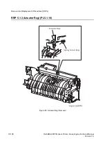
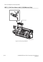
Page 396: ...12 26 Hakuba 26PPM Laser Printer Base Engine Technical Manual Version 1 0 Parts List...

Page 397: ...mission to the Fuser Assy 13 21 Drive Transmission tothe Exit Components 13 22 HAKUBA Main Component Function 13 23 1 Covers PL1 13 24 2 Paper Cassette PL2 13 25 3 Paper Feeder PL3 13 26 4 Chute MBF P...

Page 398: ...oltage Power Supply 13 66 Printer Controls 13 67 Paper Size Bit configuration STATUS 5 13 67 Paper Timing 13 68 E2 Paper Jam Timing 13 68 E3 Paper Jam Timing 13 69 E4 Paper Jam Timing 13 70 ROS Contro...

Page 399: ...Discharge 6 Fusing 7 Cleaning Figure 1 illustrates the HAKUBA print cycle It shows the sequence of events for the xerographic process and the paper flow into and out of the printer Figure 2 on the fo...

Page 400: ...13 4 HAKUBA 26PPM Laser Printer Base Engine Technical Manual Version 1 0 Principles of Operation Figure 2 Side view block diagram of the print cycle...

Page 401: ...remains in darkness Light striking the drum discharges the surface charge The BCR is a conductive roll that is positioned slightly above the surface of the drum The PWBA HVPS supplies the BCR with two...

Page 402: ...ulates this beam turning it on and off according to image information Through the use of a series of rotating and stationary mirrors within the ROS Assy the beam scans the negative charged drum surfac...

Page 403: ...the toner on the Magnetic Roll and makes toner transfer easier The Magnetic Roll maintains an electrical potential qrelative to the charged surface of the drum Nega tive charged areas of the drum have...

Page 404: ...d the drum surface This positive charge transfers the negative charged toner image from the drum surface to the front of the paper The toner image is now on the paper and the paper is now stuck to the...

Page 405: ...f the paper the Detack Saw a thin strip of metal that resembles a saw blade applies a negative charge to the back side of the paper to neutralize the positive voltage that was applied to it by the BTR...

Page 406: ...ing Blade removes any toner that remains on the drum after the transfer process Immedi ately after passing the Cleaning Blade the drum passes under the BCR The BCR applies an AC volt age to the surfac...

Page 407: ...rinter Base Engine Technical Manual 13 11 Version 1 0 Principles of Operation The Changes in the Electrical Potential of the Drum Surface During the Print Cycle Figure 9 Drum Image and Corresponding D...

Page 408: ...three paths that a sheet of paper can follow during a print cycle Figure 10 One path is taken if paper is fed from the paper cassette Another path is taken if paper is fed from the Multiple Bypass Fee...

Page 409: ...Manual 13 13 Version 1 0 Principles of Operation Figure 11 is a cut away side view of the HAKUBA printer that shows the major components that are directly related to the paper path Figure 11 Cut away...

Page 410: ...Image Path Figure 12 shows how the printer converts the electronic image sent from your computer into a printed image on a sheet of paper Figure 13 shows the major components that are directly relate...

Page 411: ...at is created by the Motor Assy Main and transmits it to four printer subsystems the Clutch Assy Turn the drum gear of CRU the Fuser Assy Optional Envelope Feeder Assy The Motor Assy Exit provides the...

Page 412: ...energy created by the Motor Assy Main is transmitted through the Gear 14 to the Gear Pick Up that drives the Roll Assy MBF When the Solenoid Pick Up actuates it trans mits the energy from the Gear 14...

Page 413: ...urn As shown in Figure 16 the mechanical energy created by the Motor Assy Main is transmitted through the Gear Assy Drive to the Clutch Assy Turn When the Clutch Assy Turn actuates it transmits the en...

Page 414: ...As shown in Figure 17 the mechanical energy created by the Motor Assy Main is transmitted through the Gear Assy Drive Clutch Assy Turn idle gears to the Clutch Assy Feed When the Clutch Assy Turn and...

Page 415: ...peration Drive Transmission to the Roll Regi Rubber As shown Figure 18 the mechanical energy created by the Motor Assy Main is transmitted through the Gear Assy Drive to the Clutch Regi that is locate...

Page 416: ...tion Drive Transmission to the Drum and the BTR the Motor Assy Main is transmitted through the Gear Assy Drive to the Drum drive gear that is located on the end of the Drum The Drum drives the Gear BT...

Page 417: ...r Assy As shown in Figure 20 the mechanical energy created by the Motor Assy Main is transmitted through the Gear Assy Drive to the Gear Idler of the Fuser Assy The Gear Idler transmits energy to the...

Page 418: ...o the Exit components As shown in Figure 21 the mechanical energy created by the Motor Assy Exit is transmitted through a small gears to the three Gears Gear Exit 17 Those Gears are located on the Rol...

Page 419: ...ain Component Function The following sections describe the function of the major components of the HAKUBA Laser Printer 1 Covers PL1 6 Chute Trans Fuser PL6 2 Paper Cassette PL2 7 Exit PL7 3 Paper Fee...

Page 420: ...the Latch Assy R so you can open the Cover Assy Front Tray Assy MBF The paper tray for use with the Multibypass Feeder MBF Chute ENV and Chute MBF The paper path components that are used with the opti...

Page 421: ...the Frame and actuates the Paper Size Switches on the PWBA Size 1 The pattern of actuated Size Switches signals the size of the paper that is loaded in the paper cassette Motor Assy Adjusts the face o...

Page 422: ...onsists of the Support Assy Nudger Shaft Feed and Roll Assy The task of this assy is to pick the paper from the Cassette Assy and feed it to the Roll Assy Turn To ensure this task the Support Assy Nud...

Page 423: ...HAKUBA 26PPM Laser Printer Base Engine Technical Manual 13 27 Version 1 0 Principles of Operation Figure 24 Components of the Paper Feeder...

Page 424: ...MBF Roll Assy MBF and the Cam Pick Up MBF This assy picks the paper from the Tray Assy MBF Solenoid Pick Up Controls the start and stop of the rotation of the Roll Assy MBF This engages the Gear Pick...

Page 425: ...nitors the level of toner remaining in the CRU Retard Assembly Prevents the MBF Roll Assembly from feeding more than one sheet of paper at a time Clutch Regi Consists of the gear and the magnetic clut...

Page 426: ...f paper as it travels between the BTR and the surface of the drum The positive charge attracts the negative charged toner image on the drum and the image transfers to the paper BTR Chute Assy Uses the...

Page 427: ...sheet of paper in order to melt the toner The negative charge that builds up on the Heat Roll is shunted through a diode to frame ground Pressure Roll A solid rubber coated metal shaft that presses th...

Page 428: ...13 32 HAKUBA 26PPM Laser Printer Base Engine Technical Manual Version 1 0 Principles of Operation Figure 28 Components of the Chute Trans Fuser 2 2 Fuser Assy...

Page 429: ...or to the optional OCT Mailbox or Duplex Assy Gate Exit Switches the paper exit path to either the face down output tray or to the optional OCT or Mailbox if installed Sensor Photo Exit Actuator Full...

Page 430: ...ked loop PLL for speed control Figure 30 shows the signal states for three speeds Figure 31 is a block schematic diagram of the scanner driver Refer to Figure 30 The PLL compares the phase of the fall...

Page 431: ...HAKUBA 26PPM Laser Printer Base Engine Technical Manual 13 35 Version 1 0 Principles of Operation Figure 30 Scanner Motor Control Timing...

Page 432: ...13 36 HAKUBA 26PPM Laser Printer Base Engine Technical Manual Version 1 0 Principles of Operation Figure 31 Block Schematic Diagram of the Scanner Driver...

Page 433: ...ccording to image information The Current Switching Circuit switches the Laser Diode On and Off according to nP DATA sent by the PWBA HKB26 MCU When nP DATA is LOW the laser is ON When P DATA is HIGH...

Page 434: ...enerates the drive power Gear Assy Drive Transmits the drive power created by the Motor Assy Main to the Paper Feeder the Fuser Assy the CRU and the Optional Envelope Feeder Assy Sensor Assy CRU The C...

Page 435: ...toner left on the drum from the last print cycle Drum Shutter When the CRU is in place in the printer and the Front Cover is closed the Drum Shutter opens to expose the area of the drum surface that...

Page 436: ...13 40 HAKUBA 26PPM Laser Printer Base Engine Technical Manual Version 1 0 Principles of Operation Figure 36 CRU Side View and Shutter...

Page 437: ...d the PWBA Size Option This receives and sends the signals information data and electric power The Switch Size is mounted on this PWBA which detects the paper size loaded in the Cassette through the c...

Page 438: ...ive components 4 Controls the printing process 5 Distributes DC power from the PWBA LVPS to other printer compo nents PWBA HVPS The High Voltage Power Supply Assy supplies high voltage AC and DC to th...

Page 439: ...HAKUBA 26PPM Laser Printer Base Engine Technical Manual 13 43 Version 1 0 Principles of Operation Figure 37 Electrical Components...

Page 440: ...nts 5 Monitors printer status such as the Fan Alarm 6 Maintains a running print count 7 Writes the NVRAM settings 8 Controls printer optional devices 9 Interfaces with the outer computer to be used th...

Page 441: ...ter turns itself into the Power on condition such as those of following ROS Condition The ROS PAUSE is selected Exit tray Selection The STANDARD STACKER is selected Misprint Mode The MISPRINT is relea...

Page 442: ...tus Busy The MCU holds this signal Low when it is sending a command This signal is not Low when CBSY is Low or CPRDY is High RDY MCU Controller Ready The MCU holds this signal Low when it receives PRF...

Page 443: ...nsmission rate CCLK 2 16 s Data length 8 bits Data check Odd parity Transmission order MSB first Signal lines CMD command STA status Data format Command Format Commands lengths range from 1 5 bytes Th...

Page 444: ...er and the following bytes except the last byte After the last byte is received the printer returns a status N which corresponds to the header code Command errors The MCU checks the received command f...

Page 445: ...uests Status 13 STATUS 13 Exit selection STATUS 14 REQUEST 1C Requests Status 14 STATUS 14 Size of envelope on Envelope Feeder STATUS 15 REQUEST 1F Requests Status 15 STATUS 15 Remaining amount of ton...

Page 446: ...STATUS 0 Printer state START 62 Start indication STATUS 0 Printer state TEST PRINT 64 Indication of start test print STATUS 0 Printer state SET CUSTOM SIZE 67 Set custom size STATUS 0 Printer state P...

Page 447: ...cation STATUS 0 Printer state SNR STATUS1 REQUEST 86 Read out the state of sensors SNR STATUS1 Paper path sensors SNR STATUS1 REQUEST 89 Read out the state of sensors SNR STATUS2 Cover sensors SNR STA...

Page 448: ...ion 1 0 Principles of Operation Timing Sequence for Simplex Printing T1 361 82 s for 600dpi 180 91 s for 1200dpi T2 110ms T3 Dependent on paper size and dot per inch T4 56 730ns for 600dpi 14 183ns fo...

Page 449: ...ngine Technical Manual 13 53 Version 1 0 Principles of Operation Simplex Page Sequence In Simplex Mode one side of each sheet of paper is printed according to the corresponding image data for that pag...

Page 450: ...13 54 HAKUBA 26PPM Laser Printer Base Engine Technical Manual Version 1 0 Principles of Operation Simplex Printing Timing engine po042FA...

Page 451: ...is sent t4 The time from transmission TOP signal until starting the next START signal sampling T4 T5 T3 Paper Size t4 sec Main Top Aux 1 Mid Aux 2 Bot MBF Env Index Card TBD Postcard TBD Monarch TBD...

Page 452: ...Size t5 sec Index Card TBD Postcard TBD Monarch TBD A5 TBD Statement TBD DL TBD C5 TBD Com 10 TBD B5 ISO TBD B5 JIS TBD Executive TBD Letter TBD A4 TBD Legal 13 TBD Legal 14 TBD Universal Custom TBD...

Page 453: ...PM Laser Printer Base Engine Technical Manual 13 57 Version 1 0 Principles of Operation t7 The duration while Feed Status is 1 Feeding Tray t7 sec Main TBD Aux1 Middle TBD Aux2 Bottom TBD MBF TBD Env...

Page 454: ...s of Operation Timing When an Error Occurs 1 Timing When the Printer Runs Out of Paper When the MCU receives a signal from the Sensor Photo No Pap 1 it sets RDY High t8 seconds after paper feed begins...

Page 455: ...13 59 Version 1 0 Principles of Operation Timing When an Error Occurs Chart Values t8 The time from when the MCU sets the TOP signal High after the last sheet is fed to when the MCU notifies the Contr...

Page 456: ...0 Principles of Operation Timing When an Error Occurs 2 Timing When Misfeed Jam Occurs When misfeed is detected MCU sets RDY signal High and keeps TOP High t9 Detection time of misfeed jam Feeding Tra...

Page 457: ...Operation Timing When an Error Occurs 3 Timing When There is a Registration Jam When a registration jam is detected the MCU sets RDY to High t10 seconds after sending TOP The MCU stops sending the BD...

Page 458: ...ngine Technical Manual Version 1 0 Principles of Operation Timing When an Error Occurs 4 Timing When There is an Exit Jam When an exit jam is detected the MCU sets RDY High t12 seconds after sending T...

Page 459: ...s of Operation Other Paper Feed Timing 1 Paper Feeder Switching During a Print Cycle The Controller uses the SELECT TRAY command to select which paper feeder to use The Controller then sets START Low...

Page 460: ...13 64 HAKUBA 26PPM Laser Printer Base Engine Technical Manual Version 1 0 Principles of Operation Command and Status Timing The command status timing charts are shown in below...

Page 461: ...as built in over current protection If an excessive current begins to flow in the 5VDC A or 24VDC circuits all DC supplies are shut down If an excessive current begins to flow in the 5VDC B or 3 3VDC...

Page 462: ...s for the BCR BTR DB and DTS The HVPS receives 24VDC input from the LVPS along with nine control signals from the MCU The HVPS has built in overcurrent protection If an excessive current begins to flo...

Page 463: ...3 shows the paper size regarding Main Tray Table H 3 Paper Size Bit Configuration PS5 PS4 PS3 PS2 PS1 PS0 HEX Paper Size 0 0 0 0 0 0 0H No Cassette installed 0 0 0 0 0 1 1H A4 0 0 0 1 0 0 4H Letter 0...

Page 464: ...E4 2 jam timing E2 Paper Jam Timing E2 0 Specified Time is a time interval from Feed Solenoid actuation to just before Registration Sensor actuation If the paper actuates the Registration Sensor befo...

Page 465: ...ples of Operation E3 Paper Jam Timing E3 1 and E3 2 Specified Time are time interval from Sensor Photo Regi to Exit Sensor of the Fuser Assy If the paper does not actuate the Exit Sensor before the E3...

Page 466: ...f Operation E4 Paper Jam Timing E4 2 and E4 3 Specified Time are time interval from Sensor Photo Regi to Sensor Photo Exit s deactua tion If the paper does not deactuate the Sensor Photo Exit before t...

Page 467: ...for the SOS signal is approx imately 98 of the SOS interval when the ROS Motor is rotating at the rated speed of 277 41 s for 600 dpi and 138 71 s for 1200 dpi ROS Motor and LD Control in Various Prin...

Page 468: ...within specified seconds after start of warm up ROS speed too low Down Failure SOS signal intervals are longer than the set Down Failure interval after completion of warm up The set Down Failure is a...

Page 469: ...hen the Heat Roll reaches the current control Temperature If the Fuser Temperature is below 100 C at start of warm up then warm up finishes when the Fuser temperature reaches standby temperature minus...

Page 470: ...ATURE CHECK software diagnosis displays the contents of NVRAM FUSER TEMP SET Temperature name Temperature value High Trouble Temperature Approximately 215 o C Standby temperature approximately 35 o C...

Page 471: ...the print cycle interruption such as closing the covers clearing the paper jam reinstalling the Paper Cassette or switching on printer power the printer runs an Erase Cycle before continuing with the...

Page 472: ...Control The printer switches between two Fan speeds High Speed when the Motor Assy Main is on Low Speed when the Motor Assy Main is off When printer power is switched on or when an Interlock Switch is...

Page 473: ...8 DB3 PWBA HKB26 MCU PWBA HVPS BTR CRU and Fuser Assy 14 10 DB4 PWBA HKB26 MCU Fuser Assy 14 13 DB5 PWBA HKB26 MCU Sensor Photo Exit and Switch Assy I L Rear 14 15 DB6 PWBA HKB26 MCU PWBA Size 1 PWBA...

Page 474: ...14 2 HAKUBA 26PPM Laser Printer Base Engine Technical Manual Version 1 0 Wiring Diagrams and Interconnections Blank Page...

Page 475: ...ter The Master Wiring Diagram shows the interconnections of the major subsystems within the printer The remainder of this sec tion divides the Master Wiring Diagram into nineteen individual diagram bl...

Page 476: ...WITH THE NEGATIVE PROBE OF THE METER ON SG THE VOLTAGE VALUE OF A SIGNAL The voltage goes LOW when the signal is ON In this case the HEAT signal is ON so the normal volt age of 3 3VDC drops to 0VDC A...

Page 477: ...HAKUBA 26PPM Laser Printer Base Engine Technical Manual 14 5 Version 1 0 Wiring Diagrams and Interconnections Master Wiring Diagram...

Page 478: ...14 6 HAKUBA 26PPM Laser Printer Base Engine Technical Manual Version 1 0 Wiring Diagrams and Interconnections DB1 PWBA HKB26 MCU PWBA HKB PS and Fuser Assy...

Page 479: ...l LOW Level 13 13 FAN ON L M 24V 15V 12 12 HEAT L M Level 3 3V 0V 11 11 FHIGH L M Level 24V 0V 9 9 FAN ALARM L M Level 3 3V 0V Signal Name Description FAN ON Fan drive power that drives the Fan Assy w...

Page 480: ...14 8 HAKUBA 26PPM Laser Printer Base Engine Technical Manual Version 1 0 Wiring Diagrams and Interconnections DB2 PWBA PS 200 100 Fan Assy Switch Assy I L Front PWBA HKB 5VDC and PWB ESS...

Page 481: ...e following table shows the signal names for the PWBA HKB PS Fan Assy path The following table shows pin numbers and voltage levels for the PWBA HKB PS Fan Assy path Signal Name Description FAN ALARM...

Page 482: ...14 10 HAKUBA 26PPM Laser Printer Base Engine Technical Manual Version 1 0 Wiring Diagrams and Interconnections DB3 PWBA HKB26 MCU PWBA HVPS BTR CRU and Fuser Assy...

Page 483: ...ency pulse signal that provides the source of oscillation for generating the AC component of the DB Development Bias in the HVPS TR Transfer Voltage to be applied onto BTR Analog TR Transfer Voltage t...

Page 484: ...BTR CRU and Fuser Assy The following table shows the signal names for the PWBA HVPS BTR CRU and Fuser Assy path Signal Name Description CR HVPS output to the Magnet Roll DB HVPS output to the BCR TR H...

Page 485: ...HAKUBA 26PPM Laser Printer Base Engine Technical Manual 14 13 Version 1 0 Wiring Diagrams and Interconnections DB4 PWBA HKB26 MCU Fuser Assy...

Page 486: ...wing table shows pin numbers and voltage levels for the PWBA HKB26 MCU Fuser Assy path Signal Name Description EXIT Signal from the Sensor Exit This signal is Low when the Sensor Exit is activated STS...

Page 487: ...HAKUBA 26PPM Laser Printer Base Engine Technical Manual 14 15 Version 1 0 Wiring Diagrams and Interconnections DB5 PWBA HKB26 MCU Sensor Photo Exit and Switch Assy I L Rear...

Page 488: ...n numbers and voltage levels for the PWBA HKB26 MCU Fuser Assy path Signal Name Description FSTK Signal from the Sensor Photo Full Stack This signal is Low when the Sensor Photo Full Stack is activate...

Page 489: ...Base Engine Technical Manual 14 17 Version 1 0 Wiring Diagrams and Interconnections DB6 PWBA HKB26 MCU PWBA Size 1 PWBA Feeder Sensor Photo Low Paper Sensor Photo Face Control Clutch Assy Feed Clutch...

Page 490: ...l goes Low NO PAP 3 Signal from the Sensor Photo No Pap 3 equipped on the Option Feeder 3 This signal is Low when the Sensor Photo No Pap 3 is activated NO PAP 2 Signal from the Sensor Photo No Pap 2...

Page 491: ...els for the PWBA HKB26 MCU PWBA Size 1 path P33 P331 Signal Name Signal Direction P PWBA Size 1 M MCU Trigger HIGH Level LOW Level Note 17 1 TG P M Level 3 3V 0V 16 2 FD TXD P M Level 3 3V 0V 15 3 FD...

Page 492: ...signal is Low when the Sensor Photo Low paper is activated FEED 1 ON Control signal which actuates the Clutch Assy Feed TRNC OUT Control signal which actuates the Clutch Assy turn The Clutch Assy Tur...

Page 493: ...HAKUBA 26PPM Laser Printer Base Engine Technical Manual 14 21 Version 1 0 Wiring Diagrams and Interconnections DB7 PWBA HKB26 MCU Motor Assy Main Motor Assy Exit and Sensor Assy CRU...

Page 494: ...and High when not driving EXIT XA Phase XA drive signal for the stepping motor LOW when driving and High when not driving EXIT B Phase B drive signal for the stepping motor LOW when driving and High...

Page 495: ...M Laser Printer Base Engine Technical Manual 14 23 Version 1 0 Wiring Diagrams and Interconnections DB8 PWBA HKB26 MCU PWBA Conn Sensor Photo Paper Set Sensor Photo Regi Clutch Regi Toner Sensor Solen...

Page 496: ...nal is Low when the Sensor Photo Regi is activated REG CL Control signal which activates the Clutch Regi TONER Signal from the Toner Sensor This signal is Low when the Toner Sensor is activated EPRS S...

Page 497: ...ow when the Sensor Photo Regi is activated REG CL Control signal which activates the Clutch Regi TONER Signal from the Toner Sensor This signal is Low when the Toner Sensor is activated EPRS Signal fr...

Page 498: ...14 26 HAKUBA 26PPM Laser Printer Base Engine Technical Manual Version 1 0 Wiring Diagrams and Interconnections DB9 PWBA HKB26 MCU ROS Assy...

Page 499: ...ser Diode SOS IN Synchronization signal generated by the PWBA SOS which indicates the start of each scan 5VLD 5V power source to the Laser Diode 0V when the Cover Assy Front is open or the CRU is not...

Page 500: ...14 28 HAKUBA 26PPM Laser Printer Base Engine Technical Manual Version 1 0 Wiring Diagrams and Interconnections Blank Page...

Page 501: ...Printing Speed After the First Sheet Out 15 5 Paper Specifications 15 6 550 Universal Cassette 15 6 Multi Bypass Feeder MBF 15 7 Envelope Feeder Optional 15 7 Duplex Asssy Optional 15 8 Baseline Paper...

Page 502: ...z 47Hz 63Hz 220 240VAC 198 264VAC 50 60Hz 47Hz 63Hz Power consumption 100 120VAC printer Maximum consumption 800W Running 45 W Sleep Maximum current 8A 100VAC 6 66A 120VAC 240VAC printer Maximum consu...

Page 503: ...esent Severe condition 48 hours maximum at 50 60 C 85 95 RH with no condensation present Acoustic Noise submitted to ISO 7779 Standby mode TBD dB A Sleep mode Background noise only Printing mode 52 0d...

Page 504: ...J Section 1010 1040 220V 240V type is submitted to IEC 825 Class 1 laser Product Ozone Density Does not exceed 0 01ppm of ozone density TWA Time Weight Aver age measured accordance with the BAM stande...

Page 505: ...d from tray 1 2 When ROS Motor OFF the values are adjusted as follows FPOT t 4 0 600 dpi FPOT t 4 0 1200 dpi 3 When the paper is fed from other tray the values are adjusted as follows FPOT t 1 2 from...

Page 506: ...o 550 sheets of the following papers Note Automatic size sensing is not effective for the custom size paper Available paper weight for Simplex Mode is 60gsm 16lb 216gsm 80lb and for Duplex Mode 60gsm...

Page 507: ...The table shows available paper sizes and stack capacity Note Supported paper weight is 60gsm 16lb 105gsm 28lb and 190gsm Japa nese Official Postcard Width mm Length mm 76 2 215 9 127 0 355 6 Type Pa...

Page 508: ...paper sizes Note Supported paper weight is 60gsm 16lb 105gsm 28lb Custom size paper longer than JIS B5 is available only when this size is designed into the ESS Controller and only when printed in on...

Page 509: ...1805 Type Size Media recommended Transparency 216 x 279mm Letter 216 x 279mm Letter 210 x 297mm A4 1 210 x 297mm A4 Xerox P N 3R2780 US 3M P N CG3300 Xerox 3R91334 Europe Xerox P N JE001 Japan Label 2...

Page 510: ...215 9 x 279 4mm Execu tive 184 2 x 266 7mm B5 JIS 182 0 x 257 0mm B5 ISO 176 0 x 250 0mm A5 149 0 x 210 0mm Half Letter 139 7 x 215 9mm 75gsm 20lb Xerox 4000 CST MBF Dup 75gsm 20lb Xerox 4024 DP CST M...

Page 511: ...99 0x210 0 OK OK Letter 215 9x279 4 OK OK OK OK OK Executive 184 2x266 7 OK OK OK B5 JIS 182 0x257 0 OK OK OK B5 ISO 176 0x250 0 OK A5 149 0x210 0 OK OK Statement Half Let ter 139 7x215 9 OK Enve lop...

Page 512: ...Feed 0 5mm at 194mm Linear Accuracy at the 45o Angle to the Direction of Feed 1 2mm at 269mm Horizontal Accuracy Parallelism 1 2mm at 234mm Magnification Accuracy in the Direction of Feed 100 0 8 at t...

Page 513: ...conjunction with the 550 sheet Paper Cassette You can install one or two 550 Sheet Paper Feeders 550 Sheet Paper Cassette Used with the 550 Sheet Paper Feeder The cassette holds 550 sheets of paper C...

Page 514: ...15 14 HAKUBA 26PPM Laser Printer Base Engine Technical Manual Version 1 0 Printer Specifications Blank page...

Reviews: