


HAKUBA 26PPM Laser Printer - Base Engine Technical Manual
10-139
Version 1.0
Removal and Replacement Procedures (RRPs)
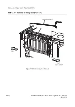
RRP 7.1.2 Actuator Full Stack (PL7.1.2) continued
Removal
1. Remove the
Cover Assy Front
(RRP 1.1.8).
2. Remove the
Cover Front L/H
(RRP 1.1.10).
3. Remove the
Cover Assy Rear
(RRP 1.2.3).
4. Remove the
Cover Assy Top
(RRP 1.1.4).
In the following steps, take care not to damage the
Actuator Full Stack
(PL7.1.2).
5. Remove the
Eliminator Assy Exit
(RRP 7.1.1).
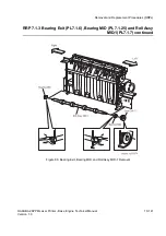
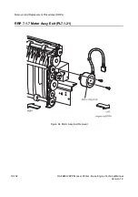
6. Raise the left shaft of
Actuator Full Stack
to remove from the left bearing of
Chute Assy
Exit
in the printer.
7. Draw the right shaft of
Actuator Full Stack
from the right bearing of
Chute Assy Exit
, and
remove the
Actuator Full Stack
.
Replacement
In the following steps, take care not to damage the
Actuator Full Stack
.
1. Insert the right shaft of
Actuator Full Stack
into the right bearing of
Chute Assy Exit
.
2. Insert the left shaft of
Actuator Full Stack
into the left bearing of
Chute Assy Exit
.
3. Mount the
Eliminator Assy Exit
(RRP 7.1.1)
4. Mount the
Cover Assy Top
(RRP 1.1.4).
5. Mount the
Cover Assy Rear
(RRP 1.2.3).
6. Mount the
Cover Front L/H
(RRP 1.1.10).
7. Mount the
Cover Assy Front
(RRP 1.1.8).
Summary of Contents for b 6100
Page 1: ...HAKUBA 26PPM Laser Printer Base Engine Technical Manual Version 1 0...
Page 8: ...viii HAKUBA 26PPM Laser Printer Base Engine Technical Manual Version 1 0 Blank Page...
Page 124: ...8 2 HAKUBA 26PPM Laser Printer Base Engine Technical Manual Version 1 0 Diagnostic Mode...
Page 146: ...8 24 HAKUBA 26PPM Laser Printer Base Engine Technical Manual Version 1 0 Diagnostic Mode...
Page 148: ...9 2 HAKUBA 26PPM Laser Printer Base Engine Technical Manual Version 1 0 Adjustment Mode...
Page 152: ...9 6 HAKUBA 26PPM Laser Printer Base Engine Technical Manual Version 1 0 Adjustment Mode...
Page 396: ...12 26 Hakuba 26PPM Laser Printer Base Engine Technical Manual Version 1 0 Parts List...


