


HAKUBA 26PPM Laser Printer - Base Engine Technical Manual
10-149
Version 1.0
Removal and Replacement Procedures (RRPs)
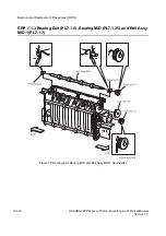
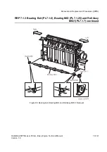
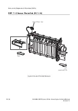
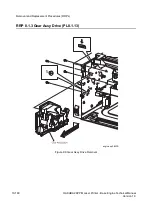
RRP 7.1.5 Sensor Photo:Exit (PL7.1.16) continued
Removal
1. Remove the
Cover Assy Front
(RRP 1.1.8).
2. Remove the
Cover Front L/H
(RRP 1.1.10).
3. Remove the
Cover Assy Rear
(RRP 1.2.3).
4. Remove the
Cover Assy Top
(RRP 1.1.4).
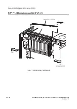
5. Remove the
Eliminator Assy Exit
(RRP 7.1.1).
6. Remove the
Actuator Full Stack
(RRP 7.1.2).
7. Unplug the connector (P/J311) on the
Sensor Photo:Exit
.
8. Disengage five hooks of
Sensor Photo:Exit
secured to the
Chute Assy Exit
in the printer.
9. Remove the
Sensor Photo:Exit
from the
Chute Assy Exit
.
Replacement
1. Aligning the position exactly, mount the
Sensor Photo:Exit
on the
Chute Assy Exit
in the
printer.
2. Secure the
Sensor Photo:Exit
to the
Chute Assy Exit
with five hooks.
3. Plug the connector (P/J311) to the
Sensor Photo:Exit
.
4. Mount the
Actuator Full Stack
(RRp 7.1.2)
5. Mount the
Eliminator Assy Exit
(RRP 7.1.1).
6. Mount the
Cover Assy Top
(RRP 1.1.4).
7. Mount the
Cover Assy Rear
(RRP 1.2.3).
8. Mount the
Cover Front L/H
(RRP 1.1.10).
9. Mount the
Cover Assy Front
(RRP 1.1.8).
Summary of Contents for b 6100
Page 1: ...HAKUBA 26PPM Laser Printer Base Engine Technical Manual Version 1 0...
Page 8: ...viii HAKUBA 26PPM Laser Printer Base Engine Technical Manual Version 1 0 Blank Page...
Page 124: ...8 2 HAKUBA 26PPM Laser Printer Base Engine Technical Manual Version 1 0 Diagnostic Mode...
Page 146: ...8 24 HAKUBA 26PPM Laser Printer Base Engine Technical Manual Version 1 0 Diagnostic Mode...
Page 148: ...9 2 HAKUBA 26PPM Laser Printer Base Engine Technical Manual Version 1 0 Adjustment Mode...
Page 152: ...9 6 HAKUBA 26PPM Laser Printer Base Engine Technical Manual Version 1 0 Adjustment Mode...
Page 396: ...12 26 Hakuba 26PPM Laser Printer Base Engine Technical Manual Version 1 0 Parts List...


