


HAKUBA 26PPM Laser Printer - Base Engine Technical Manual
10-183
Version 1.0
Removal and Replacement Procedures (RRPs)
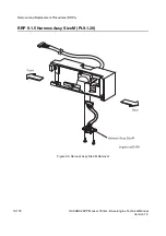
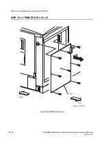
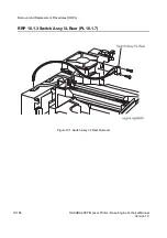
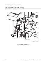
RRP 10.1.1 PWB ESS (PL10.1.2) continued
Removal
1. Remove the
Cover Assy I/F
(RRP 1.1.2).
2. Unplug the connector from the
PWB ESS
.
3. Unplug the connector from the
PWB ESS
.
4. Remove the eight screws securing the
PWB ESS
to the printer.
5. Shifting the
PWB ESS
toward the rear, unplug the connector from the printer.
6. Remove the
PWB ESS
from the printer.
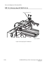
Replacement
1. Align the
PWB ESS
with its mount position to the printer.
2. Shifting the
PWB ESS
toward the front of printer, plug the connector of
PWB ESS
to the
connector of
PWBA HKB26 MCU
(PL10.1.13).
3. Secure the
PWB ESS
to the printer with eight screws.
4. Plug the connector to the
PWB ESS
.
5. Plug the connector to the
PWB ESS
.
6. Mount the
Cover Assy I/F
(RRP 1.1.2).
Summary of Contents for b 6100
Page 1: ...HAKUBA 26PPM Laser Printer Base Engine Technical Manual Version 1 0...
Page 8: ...viii HAKUBA 26PPM Laser Printer Base Engine Technical Manual Version 1 0 Blank Page...
Page 124: ...8 2 HAKUBA 26PPM Laser Printer Base Engine Technical Manual Version 1 0 Diagnostic Mode...
Page 146: ...8 24 HAKUBA 26PPM Laser Printer Base Engine Technical Manual Version 1 0 Diagnostic Mode...
Page 148: ...9 2 HAKUBA 26PPM Laser Printer Base Engine Technical Manual Version 1 0 Adjustment Mode...
Page 152: ...9 6 HAKUBA 26PPM Laser Printer Base Engine Technical Manual Version 1 0 Adjustment Mode...
Page 396: ...12 26 Hakuba 26PPM Laser Printer Base Engine Technical Manual Version 1 0 Parts List...


