


HAKUBA 26PPM Laser Printer - Base Engine Technical Manual
10-207
Version 1.0
Removal and Replacement Procedures (RRPs)
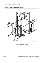
RRP 10.1.10 Main Switch (PL10.1.18) continued
Removal
1. Remove the
Cover Assy Front
(RRP 1.1.8).
2. Remove the
Cover Front L/H
(RRP 1.1.10).
3. Remove the
Cover Assy I/F
(RRP 1.1.2).
4. Remove the
Cover Left
(RRP 1.1.1).
5. Remove the
Cover Assy Top
(RRP 1.1.4).
6. Remove the
Plate Assy Left
(RRP 9.1.1).
7. Remove the
Plate Handle
(RRP 9.1.3).
In the following steps, do not detach the
Main Switch
and the
PWBA HKB PS
(PL10.1.17) far away because they are connected with the harness.
8. Remove the
PWBA HKB Assy
(RRP 10.1.9).
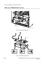
9. Push The rear of Main Switch so that it comes out of the front from the printer.
Replacement
Align the position exactly, mount the
Main Switch
on the printer with its ON side
up.
1. Align the
Main Switch
with it mount position to the printer.
2. Fit the
Main Switch
in the printer to secure.
3. Mount the
PWBA HKB Assy
(RRP 10.1.9).
4. Mount
Plate Handle
(RRP 9.1.3).
5. Mount the
Plate Assy Left
(RRP 9.1.1).
6. Mount the
Cover Assy Top
(RRP 1.1.4).
7. Mount the
Cover Left
(RRP 1.1.1).
8. Mount the
Cover Assy I/F
(RRP 1.1.2).
9. Mount the
Cover Front L/H
(RRP 1.1.10).
10. Mount the
Cover Assy Front
(RRP 1.1.8).
Summary of Contents for b 6100
Page 1: ...HAKUBA 26PPM Laser Printer Base Engine Technical Manual Version 1 0...
Page 8: ...viii HAKUBA 26PPM Laser Printer Base Engine Technical Manual Version 1 0 Blank Page...
Page 124: ...8 2 HAKUBA 26PPM Laser Printer Base Engine Technical Manual Version 1 0 Diagnostic Mode...
Page 146: ...8 24 HAKUBA 26PPM Laser Printer Base Engine Technical Manual Version 1 0 Diagnostic Mode...
Page 148: ...9 2 HAKUBA 26PPM Laser Printer Base Engine Technical Manual Version 1 0 Adjustment Mode...
Page 152: ...9 6 HAKUBA 26PPM Laser Printer Base Engine Technical Manual Version 1 0 Adjustment Mode...
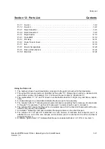
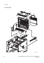
Page 396: ...12 26 Hakuba 26PPM Laser Printer Base Engine Technical Manual Version 1 0 Parts List...


