


Hakuba 26PPM Laser Printer - Base Engine Technical Manual
12-1
Version 1.0
Parts List
Section 12 - Parts List
Contents
PL1.1 Covers I . . . . . . . . . . . . . . . . . . . . . . . . . . . . . . . . . . . . . . . . . . . . . . . . . . . . . . . . . . . . . . . . 12-2
PL1.2 Covers II . . . . . . . . . . . . . . . . . . . . . . . . . . . . . . . . . . . . . . . . . . . . . . . . . . . . . . . . . . . . . . . 12-4
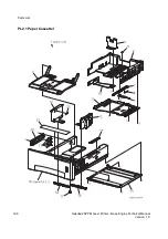
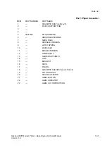
PL2.1 Paper Cassette I . . . . . . . . . . . . . . . . . . . . . . . . . . . . . . . . . . . . . . . . . . . . . . . . . . . . . . . . . 12-6
PL2.2 Paper Cassette II. . . . . . . . . . . . . . . . . . . . . . . . . . . . . . . . . . . . . . . . . . . . . . . . . . . . . . . . . 12-8
PL3.1 Paper Feeder. . . . . . . . . . . . . . . . . . . . . . . . . . . . . . . . . . . . . . . . . . . . . . . . . . . . . . . . . . . 12-10
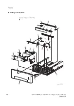
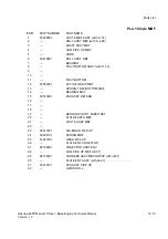
PL4.1 Chute MBF . . . . . . . . . . . . . . . . . . . . . . . . . . . . . . . . . . . . . . . . . . . . . . . . . . . . . . . . . . . . 12-12
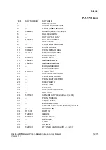
PL5.1 P/H Assy . . . . . . . . . . . . . . . . . . . . . . . . . . . . . . . . . . . . . . . . . . . . . . . . . . . . . . . . . . . . . . 12-14
PL6.1 Chute Trans & Fuser . . . . . . . . . . . . . . . . . . . . . . . . . . . . . . . . . . . . . . . . . . . . . . . . . . . . . 12-16
PL7.1 Exit. . . . . . . . . . . . . . . . . . . . . . . . . . . . . . . . . . . . . . . . . . . . . . . . . . . . . . . . . . . . . . . . . . . 12-18
PL8.1 Drive & Xerographics. . . . . . . . . . . . . . . . . . . . . . . . . . . . . . . . . . . . . . . . . . . . . . . . . . . . . 12-20
PL9.1 Frame & Size Sensor . . . . . . . . . . . . . . . . . . . . . . . . . . . . . . . . . . . . . . . . . . . . . . . . . . . . 12-22
PL10.1 Electrical . . . . . . . . . . . . . . . . . . . . . . . . . . . . . . . . . . . . . . . . . . . . . . . . . . . . . . . . . . . . . . 12-24
Using the Parts List
1. The numbers shown in each illustration correspond to the parts list number for that illustration.
2. Throughout this manual, parts are identified by the prefix “PL”, followed by a number, a decimal point,
and another number. For example, PL3.1.12 means the part is item 12 of parts list 3.1.
3. The capital letters “C”, “E”, and “S” shown in an illustration stand for C-ring, E-ring, and Screw, respec-
tively.
4. A shaded triangle t in an illustration indicates the item is part of an assembly.
5. The notation “with X~Y” following an part name indicates an assembly that is made up of components
X through Y. For example, “1 (with 2~4)” means part 1 consists of part 2, part 3, and part 4.
6. The notation "RS" means that the part is a requested spare. Part numbers for these parts will be pro-
vided as soon as they are available.
7. An asterisk
*
following a part name indicates the page contains a note about this part.
8. The notation “J1<>J2 and P2” is attached to a wire harness. It indicates that connector jack 1 is
attached to one end of the wire harness and connector jack 2 is attached to the other end that is
plugged into plug 2.
9. A notation "(part of item 1.1)" indicates that the part is included with item 1.2.1 (PL1.2, line item 1).
Summary of Contents for b 6100
Page 1: ...HAKUBA 26PPM Laser Printer Base Engine Technical Manual Version 1 0...
Page 8: ...viii HAKUBA 26PPM Laser Printer Base Engine Technical Manual Version 1 0 Blank Page...
Page 124: ...8 2 HAKUBA 26PPM Laser Printer Base Engine Technical Manual Version 1 0 Diagnostic Mode...
Page 146: ...8 24 HAKUBA 26PPM Laser Printer Base Engine Technical Manual Version 1 0 Diagnostic Mode...
Page 148: ...9 2 HAKUBA 26PPM Laser Printer Base Engine Technical Manual Version 1 0 Adjustment Mode...
Page 152: ...9 6 HAKUBA 26PPM Laser Printer Base Engine Technical Manual Version 1 0 Adjustment Mode...
Page 396: ...12 26 Hakuba 26PPM Laser Printer Base Engine Technical Manual Version 1 0 Parts List...


