


13-34
HAKUBA 26PPM Laser Printer - Base Engine Technical Manual
Version 1.0
Principles of Operation
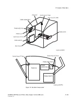
8- Drive & Xerographics (PL8)
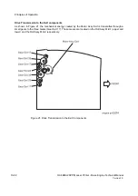
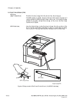
ROS Assy
The Raster Output Scanner Assy is the laser and the scanning hardware.
The ROS is made up of three major components; the Laser Diode Assy,
the Scanner Assy, and the PWBA SOS.
LD Assy (Laser Diode Assy):
Converts electrical signals into optical sig-
nals. The LD Assembly generates the laser beam and maintains the laser
output power at a constant level.
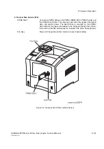
Scanner Assy:
Routes the laser beam to the drum, and scans it across
the drum surface. The Scanner Assy consists of a fifteen sided Polygon
Mirror that is attached to the Scanner Motor. The Motor rotates at a con-
stant speed. The spinning Polygon Mirror reflects the beam, through a
series of lens and mirrors, onto the rotating drum surface. The movement
of the spinning Polygon Mirror scans the beam from one side of the drum
to the other; one scan line per mirror facet. This process repeats until the
controller stops sending image data to the laser.
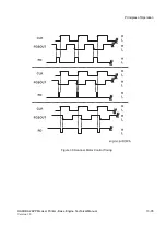
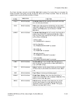
The Scanner Motor uses a phase-locked loop (PLL) for speed control.
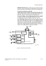
Figure 30 shows the signal states for three speeds. Figure 31 is a block
schematic diagram of the scanner driver.
Refer to Figure 30. The PLL compares the phase of the falling edge of the
output signal from the Schmitt frequency generator (FG) with the rising
edge of the Clock Signal (CLK). The output of the PLL is a voltage that is
proportional to the differences in the phase of FG and CLK. The output is
the phase detect (PD).
PD pulse duration indicates the amount of signal deviation observed. The
frequency generator generates 15 pulses during each revolution of the
Scanner Motor. A smoothing filter, using an integrating amplifier, converts
the PD signal into a voltage value. The voltage is used as the feed-back
to control the speed of the motor.
The Scanner Motor is driven by a three-phase, full-wave, linear drive. The
current to the motor coil is switched by a Hall amplifier matrix that uses
the signals from the PD to signal when to switch phases.
The signal /SCN MOT ON, from the PWBA HKB26 MCU, switches the
Scanner ON. The signals SPI1 and SPI2 select a ratio of frequency divi-
sion of the Clock signal. This ratio switches the resolution of the scanned
image. The signals are always at HIGH, so the resolution cannot be
switched.
Summary of Contents for b 6100
Page 1: ...HAKUBA 26PPM Laser Printer Base Engine Technical Manual Version 1 0...
Page 8: ...viii HAKUBA 26PPM Laser Printer Base Engine Technical Manual Version 1 0 Blank Page...
Page 124: ...8 2 HAKUBA 26PPM Laser Printer Base Engine Technical Manual Version 1 0 Diagnostic Mode...
Page 146: ...8 24 HAKUBA 26PPM Laser Printer Base Engine Technical Manual Version 1 0 Diagnostic Mode...
Page 148: ...9 2 HAKUBA 26PPM Laser Printer Base Engine Technical Manual Version 1 0 Adjustment Mode...
Page 152: ...9 6 HAKUBA 26PPM Laser Printer Base Engine Technical Manual Version 1 0 Adjustment Mode...
Page 396: ...12 26 Hakuba 26PPM Laser Printer Base Engine Technical Manual Version 1 0 Parts List...


