


13-46
HAKUBA 26PPM Laser Printer - Base Engine Technical Manual
Version 1.0
Principles of Operation
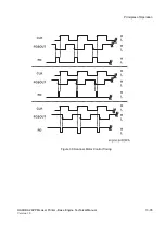
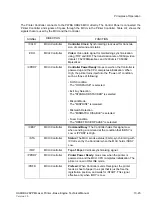
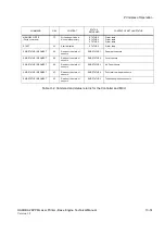
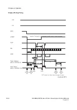
Table H-1. Signals that are used between the MCU and the Controller
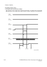
/CMD
MCU<Controller
Command:
Command signal. The Controller sends a
command (8 bits); synchronizing with /CCLK, and holding /
CBSY Low.
/START
MCU<Controller
START:
Signal telling the printer to start the print operation.
This signal is valid when /RDY is Low.
/SBSY
MCU>Controller
Status Busy:
The MCU holds this signal Low when it is
sending a command. This signal is not Low when /CBSY is
Low or /CPRDY is High.
/RDY
MCU>Controller
Ready:
The MCU holds this signal Low when it receives /
PRFD and /START. When /RDY is High, /PRFD and /
START are ignored.
/RDY goes High when the printer is in one of the following
states:
1. Call
2. Pause/Diag
3. Wait
4. Misprint
5. /PPRDY set High
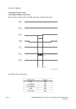
/BD
MCU>Controller
Beam Detect
: Horizontal synchronization signal. The
Controller transmits the one line of video data that is
synchronized with this signal.
The period of the /BD signal is 361.82 s for 600 dpi and
180.91 s for 1200 dpi.
SIGNAL
DIRECTION
FUNCTION
Summary of Contents for b 6100
Page 1: ...HAKUBA 26PPM Laser Printer Base Engine Technical Manual Version 1 0...
Page 8: ...viii HAKUBA 26PPM Laser Printer Base Engine Technical Manual Version 1 0 Blank Page...
Page 124: ...8 2 HAKUBA 26PPM Laser Printer Base Engine Technical Manual Version 1 0 Diagnostic Mode...
Page 146: ...8 24 HAKUBA 26PPM Laser Printer Base Engine Technical Manual Version 1 0 Diagnostic Mode...
Page 148: ...9 2 HAKUBA 26PPM Laser Printer Base Engine Technical Manual Version 1 0 Adjustment Mode...
Page 152: ...9 6 HAKUBA 26PPM Laser Printer Base Engine Technical Manual Version 1 0 Adjustment Mode...
Page 396: ...12 26 Hakuba 26PPM Laser Printer Base Engine Technical Manual Version 1 0 Parts List...