


HAKUBA 26PPM Laser Printer - Base Engine Technical Manual
13-65
Version 1.0
Principles of Operation
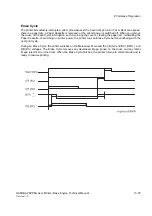
Power Supplies
The LVPS (Low Voltage Power Supply)
The LVPS uses a resonance-type switching regulator. The LVPS su24VDC, +5VDC, +3.3VDC (A),
and +5VDC (B). The +5VDC (B) is labeled as 5V INTLK in the printer wiring diagrams.
The LVPS has built-in over current protection. If an excessive current begins to flow in the +5VDC(A) or
+24VDC circuits, all DC supplies are shut down. If an excessive current begins to flow in the +5VDC (B) or
+3.3VDC circuits, only the +24VDC supplies are shut down. Switch the power supply OFF, then ON again
to reset the circuit after an over current shutdown.
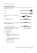
The LVPS also supplies AC power to the Heat Rod. A circuit, controlled by the Heat ON signal from the
MCU, switches power to the Heat Rod.
Figure 39. PWBA HKB PS Schematic Block Diagram
Summary of Contents for b 6100
Page 1: ...HAKUBA 26PPM Laser Printer Base Engine Technical Manual Version 1 0...
Page 8: ...viii HAKUBA 26PPM Laser Printer Base Engine Technical Manual Version 1 0 Blank Page...
Page 124: ...8 2 HAKUBA 26PPM Laser Printer Base Engine Technical Manual Version 1 0 Diagnostic Mode...
Page 146: ...8 24 HAKUBA 26PPM Laser Printer Base Engine Technical Manual Version 1 0 Diagnostic Mode...
Page 148: ...9 2 HAKUBA 26PPM Laser Printer Base Engine Technical Manual Version 1 0 Adjustment Mode...
Page 152: ...9 6 HAKUBA 26PPM Laser Printer Base Engine Technical Manual Version 1 0 Adjustment Mode...
Page 396: ...12 26 Hakuba 26PPM Laser Printer Base Engine Technical Manual Version 1 0 Parts List...