


HAKUBA 26PPM Laser Printer - Base Engine Technical Manual
14-3
Version 1.0
Wiring Diagrams and Interconnections
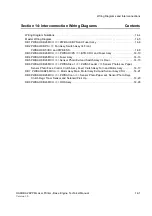
Section 14: Interconnection Wiring Diagrams
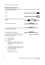
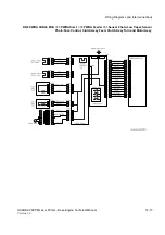
This section of the manual contains a Master Wiring Diagram for the Asama printer. The Master Wiring
Diagram shows the interconnections of the major subsystems within the printer. The remainder of this sec-
tion divides the Master Wiring Diagram into nineteen individual diagram blocks (DB) to better illustrate the
electrical relationships between components and assemblies within the printer. Each wire in the diagram
blocks is tagged with a signal name, and each wire is terminated at both ends with a pin number.
Summary of Contents for b 6100
Page 1: ...HAKUBA 26PPM Laser Printer Base Engine Technical Manual Version 1 0...
Page 8: ...viii HAKUBA 26PPM Laser Printer Base Engine Technical Manual Version 1 0 Blank Page...
Page 124: ...8 2 HAKUBA 26PPM Laser Printer Base Engine Technical Manual Version 1 0 Diagnostic Mode...
Page 146: ...8 24 HAKUBA 26PPM Laser Printer Base Engine Technical Manual Version 1 0 Diagnostic Mode...
Page 148: ...9 2 HAKUBA 26PPM Laser Printer Base Engine Technical Manual Version 1 0 Adjustment Mode...
Page 152: ...9 6 HAKUBA 26PPM Laser Printer Base Engine Technical Manual Version 1 0 Adjustment Mode...
Page 396: ...12 26 Hakuba 26PPM Laser Printer Base Engine Technical Manual Version 1 0 Parts List...