


14-12
HAKUBA 26PPM Laser Printer - Base Engine Technical Manual
Version 1.0
Wiring Diagrams and Interconnections
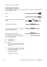
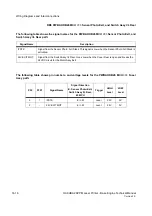
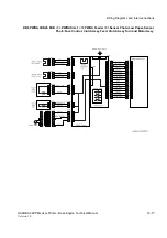
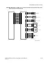
DB3 PWBA HKB26 MCU <=> PWBA HVPS <=> BTR, CRU, and Fuser Assy
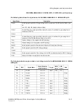
The following table shows the signal names for the PWBA HVPS <=> BTR, CRU, and Fuser Assy
path:
Signal Name
Description
CR
HVPS output to the Magnet Roll
DB
HVPS output to the BCR
TR
HVPS output to the BTR (+DC in Transfer operation, and -DC when cleaning the BTR)
DTS
HVPS output to the DTS
PRB
HVPS output to the Pressure Roll
Summary of Contents for b 6100
Page 1: ...HAKUBA 26PPM Laser Printer Base Engine Technical Manual Version 1 0...
Page 8: ...viii HAKUBA 26PPM Laser Printer Base Engine Technical Manual Version 1 0 Blank Page...
Page 124: ...8 2 HAKUBA 26PPM Laser Printer Base Engine Technical Manual Version 1 0 Diagnostic Mode...
Page 146: ...8 24 HAKUBA 26PPM Laser Printer Base Engine Technical Manual Version 1 0 Diagnostic Mode...
Page 148: ...9 2 HAKUBA 26PPM Laser Printer Base Engine Technical Manual Version 1 0 Adjustment Mode...
Page 152: ...9 6 HAKUBA 26PPM Laser Printer Base Engine Technical Manual Version 1 0 Adjustment Mode...
Page 396: ...12 26 Hakuba 26PPM Laser Printer Base Engine Technical Manual Version 1 0 Parts List...