


14-14
HAKUBA 26PPM Laser Printer - Base Engine Technical Manual
Version 1.0
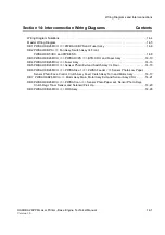
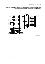
Wiring Diagrams and Interconnections
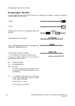
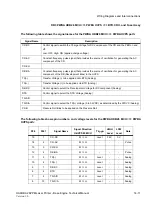
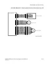
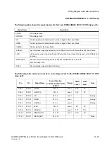
DB4 PWBA HKB26 MCU <=> Fuser Assy
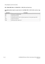
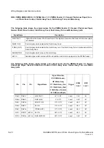
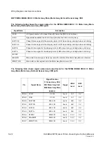
The following table shows the signal names for the PWBA HKB26 MCU <=> Fuser Assy path:
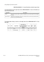
The following table shows pin numbers, and voltage levels for the PWBA HKB26 MCU <=> Fuser
Assy path:
Signal Name
Description
/EXIT
Signal from the Sensor Exit. This signal is Low when the Sensor Exit is activated.
STS
Signal from the Temperature Sensor which monitors the Fuser Heat Roll temperature. (Analog)
P27
P271
Signal Name
Signal Direction
F: Fuser M: MCU
Trigger
HIGH
Level
LOW
Level
Note
5
1
/EXIT
M <= F
Level
3.3V
0V
2
4
STS (A/D)
M <= F
Level
-
-
Analog
Summary of Contents for b 6100
Page 1: ...HAKUBA 26PPM Laser Printer Base Engine Technical Manual Version 1 0...
Page 8: ...viii HAKUBA 26PPM Laser Printer Base Engine Technical Manual Version 1 0 Blank Page...
Page 124: ...8 2 HAKUBA 26PPM Laser Printer Base Engine Technical Manual Version 1 0 Diagnostic Mode...
Page 146: ...8 24 HAKUBA 26PPM Laser Printer Base Engine Technical Manual Version 1 0 Diagnostic Mode...
Page 148: ...9 2 HAKUBA 26PPM Laser Printer Base Engine Technical Manual Version 1 0 Adjustment Mode...
Page 152: ...9 6 HAKUBA 26PPM Laser Printer Base Engine Technical Manual Version 1 0 Adjustment Mode...
Page 396: ...12 26 Hakuba 26PPM Laser Printer Base Engine Technical Manual Version 1 0 Parts List...


