


14-16
HAKUBA 26PPM Laser Printer - Base Engine Technical Manual
Version 1.0
Wiring Diagrams and Interconnections
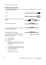
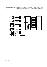
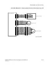
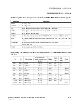
DB5 PWBA HKB26 MCU <=> Sensor Photo:Exit, and Switch Assy I/L Rear
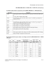
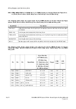
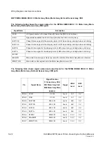
The following table shows the signal names for the PWBA HKB26 MCU <=> Sensor Photo:Exit, and
Switch Assy I/L Rear path:
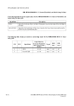
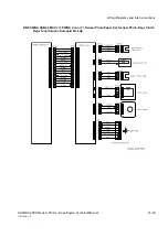
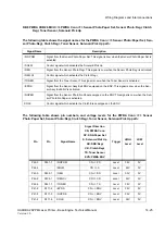
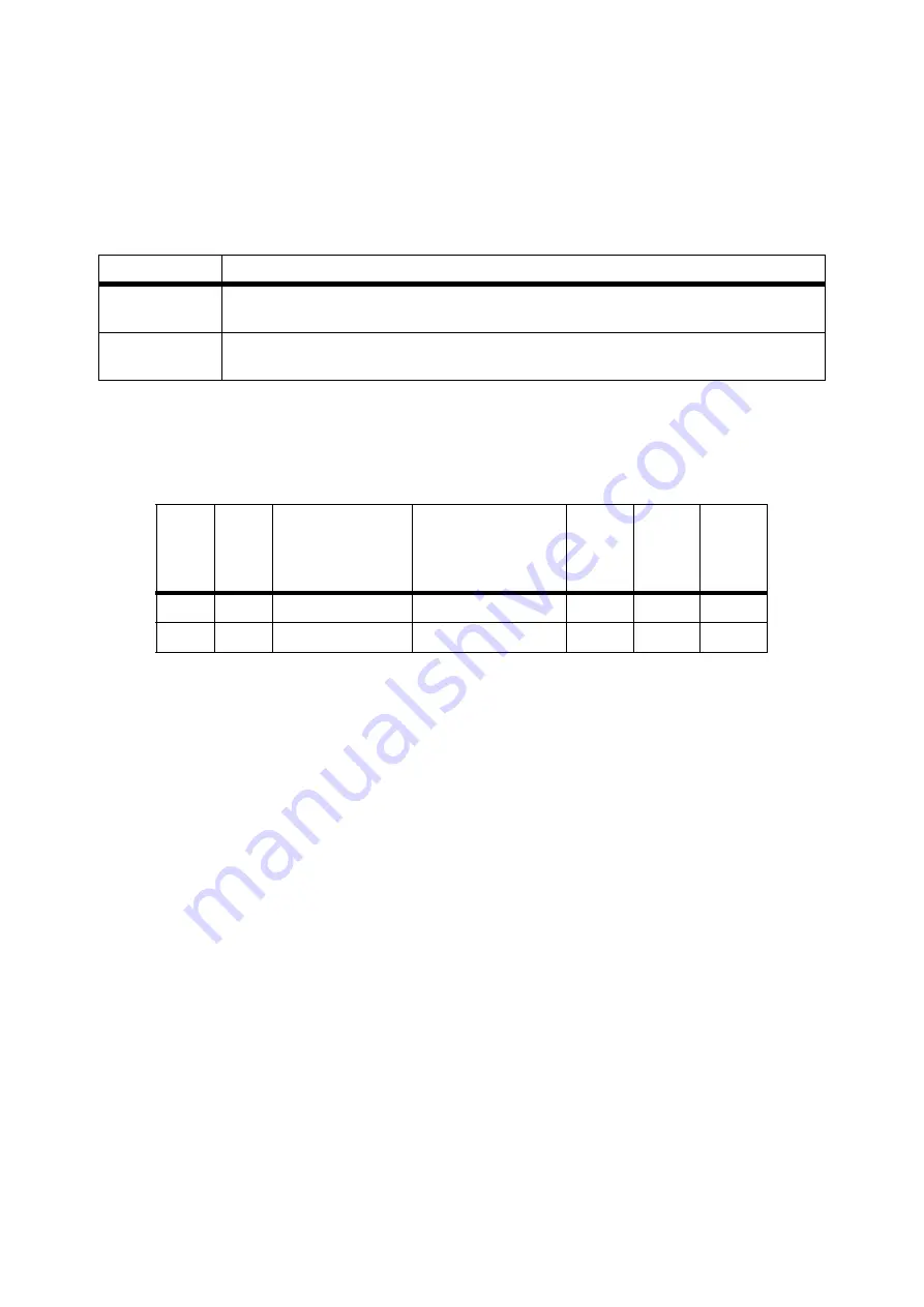
The following table shows pin numbers, and voltage levels for the PWBA HKB26 MCU <=> Fuser
Assy path:
Signal Name
Description
/FSTK
Signal from the Sensor Photo: Full Stack. This signal is Low when the Sensor Photo:Full Stack is
activated.
24V EXIT MOT
Signal from the Switch Assy I/L Rear. Goes Low when the Cover Rear is open and breaks the
24VDC circuit for the Motor Assy Exit.
P30
P301
Signal Name
Signal Direction
E: Sensor Photo:Exit,
Switch Assy I/L Rear,
M: MCU
Trigger
HIGH
Level
LOW
Level
3
1
/FSTK
E => M
Level
3.3V
0V
2
-
24V EXIT MOT
E => M
Level
24V
0V
Summary of Contents for b 6100
Page 1: ...HAKUBA 26PPM Laser Printer Base Engine Technical Manual Version 1 0...
Page 8: ...viii HAKUBA 26PPM Laser Printer Base Engine Technical Manual Version 1 0 Blank Page...
Page 124: ...8 2 HAKUBA 26PPM Laser Printer Base Engine Technical Manual Version 1 0 Diagnostic Mode...
Page 146: ...8 24 HAKUBA 26PPM Laser Printer Base Engine Technical Manual Version 1 0 Diagnostic Mode...
Page 148: ...9 2 HAKUBA 26PPM Laser Printer Base Engine Technical Manual Version 1 0 Adjustment Mode...
Page 152: ...9 6 HAKUBA 26PPM Laser Printer Base Engine Technical Manual Version 1 0 Adjustment Mode...
Page 396: ...12 26 Hakuba 26PPM Laser Printer Base Engine Technical Manual Version 1 0 Parts List...