background image

Summary of Contents for CT 2200

Page 1: ...GT 2200 GOMMUNIGATIONS TERMINAL INSTRUCTION MANUAL HAL COMMUNICATIONS CORP BOX 365 URBANA ILLINOIS 61801 QUALITY COM M U NICATIONS EQ UIPM ENT...

Page 2: ...SaU by HAL Communieations Corp Urbana I1linois Printed in the United States of America All rights reserved Contents of this publlcation may not be reproduced in any form without the written permisslon...

Page 3: ...the ttBrag tapetr Messages o t 4 T Special Consideratlons l tren Transmitting Morse o 4 8 Speclal Conslderations l hen Transmitting Baudot 4 9 Special Considerations t hen Transmitting ASCII 4 10 HDX...

Page 4: ...0 Simplified CT2200 Connections The K82100 Keyboard Morse Weight Timing Connecblons to the CT2200 KOS Clrcuit Connections RFI Reduction Teehniques RFI Powgr Llng Filtgrs o o o o RF Suppression Toroid...

Page 5: ...evices there are some features and operator techniques which you may not understand until you have read this manual You should plan to devote several hours to becoming familiar with your CT2200 Howeve...

Page 6: ...E PAGE 2 iiiii ilili iiiit Figure 1 The CT2200...

Page 7: ...ts and then notify either your dealer or HAL Com munications Corp of the shortage Please specify the HAL part number Accessory parts Aceessorles packed Wit h CTZZO z 1 333 1 7250 AC Power Cord 16 310...

Page 8: ...o o tf I J o z cO o l g lrt F o o f o3 r g r oo a 0a o o I fl a F td u t o r J o o N cn i vo io C C F c9e zEr rio i 8 f Ez il m x TE a 7 z tJ iG Il 1F ur Q r 2 orJ a z il ul r TI UE6 l J s 5 i z t 60...

Page 9: ...d audio cable between the receiver speaker audio output and the CT2200 RCVR IN conneetor 3 Connect a shielded audio cable between an external speaker 4 1 6 ohms and the CT2200 AUDIO MONITOR connector...

Page 10: ...MAN TXIAUTO KOS RTTY MODEM HIGH LOW NORM REV AUTO RTTY SHIFT AUDIO R5232 RCVE TAPE NORM LOOP OUTPUT INPUT VOLUME Now turn on the video monitor power and top Ilne of the display 45 BD BAUDOT TX OFF US...

Page 11: ...e Also the MARK and SPACE tuning LEDs on the CT22O0 front panel can be used for tuning the LED should stay on and the MARK and SPACE LEDs flash alternately You should now have ttprinttt of the receive...

Page 12: ...he receiver audio gain so that the audio output from the CT2200 MONITOR OUTPUT ls slmilar for MONITOR INPUT and OUTPUT switch settings Occasionally Vou may find that the Morse receive seetlon appears...

Page 13: ...se simple CT2200 conneetions fuII conneetions are found ln Flgure 5 in Chapter 5 If you have an external monitor speaker for your receiver you may wish to take advantage of the bullt in CT220O audio m...

Page 14: ...in off button out on button in on or off HDX button in AUTO button out off button out RTTY button in LOW button out NORM button ln off button out 850 left hand butLon in AUDIO button in RCVE button in...

Page 15: ...lines page 2 and normal video Switching line length and video polariby is a good test of your moni tor a high qua lty nonltor will not require any readjustment when making these changes Now preset you...

Page 16: ...ou can to the MARK eon dition MARK light oD tuning bar peak Use the MONITOR INPUT OUTPUT swltch to seleet 0UTPUT button in The tone you hear is the crystal synthesized AFSK output tone from the CT220O...

Page 17: ...10 8 MHz 11 1 HHz 11 5 MHz 12 2 MHz 13 5 MHz 14 5 MHz 14 9 MHz 15 5 ll l z 15 9 MHz 16 2 MHz 16 4 MHz 17 3 MHz 17 5 MHz 18 2 MHz 18 4 MHz 18 7 l Hz and 19 0 to 20 5 MHz p1us others Commereial RTTY sta...

Page 18: ...ne set are as follows HIGH TONES Mark 2125 Hz Space 2295 2550 oF ZgT5 Hz Advantages 1 High tones are the U S VHF AFSK standard their use ls required for compatlbility when operating VHF AFSK in the U...

Page 19: ...e chapter 4 there is a strong probability that over drivlng the transmiLter audio and modurator stages wil resurt in spurious harmonics and mixer products that will be radiated 0f course these problem...

Page 20: ...elected operabing off the rrcar rier detecttt slgnal from the modem integrated circuits AIso the MARK and SPACE lamps still function in M0DEM mode but the lamp Screen tuning bar and external scope out...

Page 21: ...ansmit sPeed as turned on no change for now P2 nrrrmr 72 rr nrrtrll ltt on button in either position does not affeet CII on or off HDX button ln AUTO button out off button out either position does not...

Page 22: ...ters in modern reeeivers and transceivers At normal receiver volume levels the PLL will track frequency varia tions over at least a or 100 Hz range and is therefore qulte to Ierant of slight buning er...

Page 23: ...es the Morse reeeption appears to stop or be tf locked uptf This is usually caused by reception of a carrler for some period of time The automatic speed tracking program of the CT22O0 interprets the l...

Page 24: ...e has been a problem Conversely the narrow filter may actually degrade the copy especlally if the narrow filter ilringsn on noise The de gree of problem caused by filter rlnging varies with the filter...

Page 25: ...CHAPTER 3 RECEIVING PAGE 21 Figure 3 The KB2100 Keyboard...

Page 26: ...and 4 9 In general use the KB2100 as you would a typewriter making use of the SHIFT key when requlred For example typing on just the rrlrr key will enter a number trlrt for transmltting SHIFT r1I wou...

Page 27: ...ow the NEW LINE k y allows you to edit any errors you may have made while typing Each operation of the RUB OUT key will back up the keyboard eursor one space removing any ehar acters previously occupy...

Page 28: ...t lm porbant ones Text typed on the K82100 can be entered into the CT2200 in either trKSR Modeft or ttsplit Screen Modetr As explained in Seetlon 4 3 typed text is entered on the bottom line of Page 2...

Page 29: ...d otherwise be bransmitted Under noisy conditions this helps the RTTI machine at the reeelving station maintain synch reduclng the error characters trhitsil This feature is most useful when talking to...

Page 30: ...always shows reverse bo that received AIso note that all the letters typed are capltalized this is because there is no upper lower case in Morse code Baudot ls th same ASCII code however does have va...

Page 31: ...ey as the very last key operatlon when ending a transmlssion oLherwise your CT220O may still be in transmit mode awaiting another key press rather than receivlng signals Thls can be extremely confusin...

Page 32: ...You cannot however add spaces or char acters within a line without re typing the balance of that line The cursor controls are CTRL H BS Back space move cursor one position left CTRL J LF Line feed mo...

Page 33: ...e because this message also serves for CW identlfication of RTTY slgnals IDENT k y The IDENT key functtons the same ln all codes it al ways gives a Morse code output of the contents of the left hand H...

Page 34: ...verse video section Each key typed uses one storage locatlon ineluding the NEW LINE key shown by the special rrlFn character Inclusion of the NEW LINE key does NOT cause a change of Ilne in the progra...

Page 35: ...e active at all times rBrag tapert messages may not be totally suecessful with some bulletin board systems unless the sys tem can aecept the complete message without handshaking interruptions If you u...

Page 36: ...th of the standard dot length from 1 2 to 1 1 2 times the normal dot time The CTRL 5 key combination hold CTRL down while pressing and releasing the 5 Iabeled MORSE WEIGHT on the K82100 allows you to...

Page 37: ...o transmlt the prosigns PROSIGN KEYBOARD SYUBOL KEY OPERATION e key key shift tr tr key shift tr rr t key shift u lr shift rr1 shift ft3u shlft rr4rr shift n5tr Shlft 6u n rrrr rrtr the CT2200 is show...

Page 38: ...apability of word node and transmit each eharacter as it ls typed Called ttGontinuous Modefr thls feature may be selected for only Horse transmit by selercting rrFDXx rather than ttHDXn Since the CT22...

Page 39: ...le baud rates and bhe corresponding words per minute rate are shown in Table Z The Baudot RTTY code uses 5 data bits to specify a given charaeter Since the 32 possible eombinatlons are insufficient to...

Page 40: ...operation of the NEI LINE key in Baudot HDX eonditlon causes the transmission of the sequence CR carriage return LF line feed LTRS letters As mentioned in earlier discussions ALWAYS END EACH TRANSMISS...

Page 41: ...X BELL CTRL G BLANK ESC STOP FIGS case H BRK Space conditlon for test Transmission order Bit 1 to Bit 5 Start Pulse 1 unit space CR D R J N F c K CR 4 I t a 5 It 2 Stop Pulse BAUD RATE 45 45 50 00 56...

Page 42: ...aracter 11111 is inserted into the transmit data whenever the transmltted text has Itcaught uptt wlth your keyboard typing Thus a stream of LTRS ehar acters are transmitted instead of a continuous mar...

Page 43: ...ls very convenient for RTTY operation of an amateur station The KOS circuit functlons much the same as a VOX volce controlled break in circuit of a SSB transmitter automatically eontrolling the transm...

Page 44: ...rted in the transmit buffer for transmission Each ASCII character and con trol code has a unique s1mbol that ls displayed on the CT2200 screen These symbols are shown in Table 3 The key combinations u...

Page 45: ...START OF TEXT SUBSTITUTE SYNCHRONOUS IDLE UNIT SEPARATOR VERTICAL TAB TRANST IITTI IG DISPLAT SYMBOLS SCREEN SYI IBOL D1 D2 D3 D4 EM EQ ET EC EB EX FF FS GS HT LF NK NL RS SI SO SH sx SB SY US VT FOR...

Page 46: ...1111 NUL DLE SPC SOH DC1 I sTx Dc ll ETX DC3 EOT DC4 ENQ NAK 1 ACK SYN BEL ETB I BS CAN HTEM LF SUB I VT ESC FFFS RTN GS SORS SIUS ACK acknowledge HT BEL slgnal beII LF BS back space NAK CAN caneel NU...

Page 47: ...ones four demodulators modulators RS232 and RTTY current L00P conneetlons external loop polrer supply required All data out puts are available simultaneously The N0RM L00P switch allows use of loop co...

Page 48: ...acter that can be inserted durlng pauses in the keyboard typing The idle or trdiddletr character maintains the rrythmntt of the output signal helping to keep the receiving stationrs equipment synchron...

Page 49: ...voltage loops The CTzzOA will key loop circuits up Eo 200 volts maximum and up to 120 ma maximum loop current Often the 1oop power supply is bullt into the RTTY machine Mode1 19 and Model zg ma chines...

Page 50: ...d to the ASCII printer output and will continue until the sequence rNNNNn 4Nfs ls received After ttNNNNtt the printer output is again inhlbited until either the SEL CALL code is agaln received or unti...

Page 51: ...g x ts L E o o N N F d t o l U z o ri il E tI tr3 tl Z o z t J o o o o o o z o D N g tr F 6 4 it U d 60 2L G4 o F d 6 lrJ z u t L a z e F E E E Qr Q G G O5 q o G oi E r e l ts IUU IOU ILf l n I 3 ti t...

Page 52: ...ly 3 A shielded audio cable between the transmitter microphone audlo input and the CT OO XMIT OUT conneetor A stereo phono cable can be used for this and the KOS connection des cribed next Note that t...

Page 53: ...TRANSISTOR 2OO V IOO mo CONT ECTIONS PAGE 49 TO PTT LINE POS VOLTAGE KOS CONNECTOR CONNECTION KOS CIRCUIT POSITIVE VOLTAGE r CONNECTION TO KOS CIRCUIT NEGATIVE VOLTAGE _ _t t ro Prr L NE I ruee voLrAG...

Page 54: ...O0 wlth the coil cord cable furnished This is a standard 6 conductor telephone cable Ionger lengths ean be found at loca1 electronics stores A toroid core is lncluded with the K82100 If any problems a...

Page 55: ...ie Do not be misled by some claims of direct TTL RS232 compatibility damage may be eaused to one or both unitsl The RS232 ouLput of the CT220O is approximately or 10 VDC with a 300 ohn internal reslst...

Page 56: ...code is selected for the display the data at the EXT L00P eonnector will also be 45 baud Bau dot code there is no speed or code conversion associated with the CT22O0 EXT L00P output Similar1y selectlo...

Page 57: ...l of the CT2200 data rates most popular printers cannot handle thls data nthrough putn 120 characters per second especially for llne feed and carriage return operatlons Unless your printer has extensi...

Page 58: ...SPACE to the vertical input Since these signals have a relatively Iow output level it is necessary to use an oscilloscope with amplifler stages in both the vertical and horizontal sections Use shield...

Page 59: ...ing the CT22O0 to the ARQ1000 5 8 RF Induced Problems The CTzzOO is designed to operate in close proximity to radlo frequen cy transmitting and reoeiving equipment Partieular attentlon has been paid t...

Page 60: ...able arrangements to see if the RF indueed problem can be eliminated by reducing coupling between any of the CT2200 cables and nearby coax ial lines carrylng RF power Figure 7A shows several eable arr...

Page 61: ...A PLACE RF CHOKE CLOSE TO REAR PANEL O F EQUIP 4ENT FROM TRANSMITTER TIE WRAP CONTROL WIRES AND COAX IN CLOSE PROXIMITY AND PARALLEL HIGH MU FERRITE TOROID CORE B ro HAL EQUIPMENT B RFI Reduetlon FER...

Page 62: ...In general a shielded coaxial cable feedline with low SIIR is much preferred over open wire twin Iead oF single wire feed systems The self shielding property and lower voltages present aet to make the...

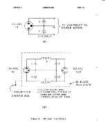
Page 63: ...CHAPTER 5 IIO VAC IN CONNECTIONS A B PAGE 59 TO EQUIPMENT AC POWER WIRING O OOlpF Figure 8 RFI Power Line Filters...

Page 64: ...srupt the monitor or CTZaOO operation This may be quickly tested by simply disconnecting the video eable from the CT2200 There is no substltute for good shielding and by passing metal cabinet monitors...

Page 65: ...g antenna relocate the computer wlth respect to the receiver move fhe computer away from the receiver plug the eomputer into a different outlet so that eomputer and reeelver are on different branch cl...

Page 66: ...her voltage range follow ihe the diagram in Figure 104 90 to 125 VAC If the power line voltage available is CONSISTENTLY lower than 110 volts the transformer can be rewired as shown in Figure 108 If h...

Page 67: ...250 VAC Connection Figure 10 Power Transforner Voltage 95 ll0 VAC Connection PAGE 63 JUMPER h JUMPER B MOVE JUMPER B REMOVE TO a b JUMPER A move roP I eruo FRoM I f To 3 JUMPER 8 REMOVE JUMPER h move...

Page 68: ...the factory and the ehange noted on the porrer llne voltage and fre quency tag on the CT2200 rear panel The four jumper locatlons are shorn in Figure 1 1 The cireuit board is construeted so that the 6...

Page 69: ...ontrol and the transmitber MIC GAIN for the desired transmitter rf output Be careful to avoid overdriving the transmitter spurious transmission may otherwise occur TAPE OUT Control The voltage level o...

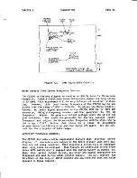
Page 70: ...d center frequency and adjust the Morse center frequency control until the CI I led is again ttlitn Notiee that there is a range of adjustment between where the LED turns on and then turns off again s...

Page 71: ...ing trgarbagert characters at this time you may improve the sibuation by adjusting the autoprint thres hold control The autoprint adjustnent potentiometer is located on the bottom side of the demodula...

Page 72: ...ture extremes as you are while operating it However inadvertent blockage of the ventilating holes in the cabinet will eause the INTERNAL temperature of the terminal to rise consider ably above the amb...

Page 73: ...ry careful KNOW the ratlngs of the CT2 00 and the charaeteristics of any other equipment befoew making conneetions Some common causes of electrlcal failures have been found Lo be A Inadequate groundin...

Page 74: ...e square block cursor in this field indicates the keyboard position within Lhe HERE IS program When the HERE IS programming is completed the status line replaces the programming field if you see the s...

Page 75: ...k with the MODEM tones but the LED indicates no useful information Similarly the CW LED ls only useful when recelving Morse code The OVLD LED indicates correctly for all audio lnput to the cT2200 9 Th...

Page 76: ...e may expeet the untt in shipping and be prepared to work on it when it arrlves tilhenever possible return the unit vla UPS to the factory address below insuring it for the fuII vaIue The shlpping cos...

Page 77: ...from external loop device MORSE Separate transistor switches to key or eircuits KEYS Voltage 150 VDC maximum Current 150 mA maxlmum SCOPE Separate mark and spaee eonnections for crossed OUTPUTS ellips...

Page 78: ...Il 128 character set may be transmitted and reeeived 8th data blt rrparity bittr set to space condition Baudot or ASCII codes nay be transmllfed and ree elved at 45 50 57 74 100 110 150 300 600 and 12...

Page 79: ...of 36 eharaeters per line 4 pages Nornar receive whlte charaeters on dark screen transmit dark eharacters on white screen Reverse receive dark characters on whlte screen transmlt white charaeters on d...

Page 80: ...hotr in FDX mode The KOS word mode word wrap around and non over print features do not function in FDX mode FDX allows simultaneous transmlt and receive operation via RS232 or audio UO connections Tra...

Page 81: ...non voratile HERE rs texts are stored in MSG2loo op tion BREAK key sends key down in Morse and spAcE condltion in RTTY modes RUB our alrows back up error correetion KEYBOARD SCREEN DATA DISPLAY INC DE...

Page 82: ...olume REAR PANEL AUDIO MONITOR EXT LOOP ASCII PRINTER RS232 IN CONNECTIONS TAPE IN RCVR IN SCOPE SPACE SCOPE MARK CW KEY P0S CII KEY NEG TAPE OUT RS232 OUT RX DATA OUT TX DATA IN XMIT OUT KOS SWITCH V...

Page 83: ...ese instruetions you find your courage faillng w will be glad to lnstall the conversion for you The HAL factory will install the up date kit for a flat eharge and return it to you as soon as possible...

Page 84: ...1 CT2200 Front Panel 1 Sticker marked tr RX DATA OUTrt 1 Sticker marked trTX DATA INrt 1 2716 IC marked CT22O0 V1 x No Ott 1 2T 16 IC marked tt CT2200 V1 x No 1 rr 1 2716 IC marked ttCT2200 V1 x No t...

Page 85: ...20O will have to be reassembred before testlng ean be done Use the No 2 Phillips screw driver to remove the top and boLtom cabinet covers Remove 6 Phillips screws on eaeh side of lhe cabinet be sure...

Page 86: ...re circuit board paths down there that can be easily damaged by the end of the screw drivert Remove all four CT2100 type 2716 ROMs Similar1y remove the MSG21OO ROM from the rear most socket lf one is...

Page 87: ...and refering to Figure 13 install each in the approprlate socket ROM nOr is closest to the front panel install 0rr rr1r tt tt I rr3rr and r4n in order from front to back Note that the pin 1 end of ea...

Page 88: ...er the three trim pot leads to replace these reslstors as shonn in Figure 17 Note that the two pot leads connecb towards the front panel and the single lead alray from the front panel This completes t...

Page 89: ...This modifieatlon is requlred to use the TRz for AMT0R set the cT2100 cablnet aside and prace the logic board in front of you with the rcts up and the switches to your righb end wibh 24 pin socket fac...

Page 90: ...ld be two 1 2n diameter holes above the labe1s TIXMIT OUTtt and IKOS SWITCHTT Very early CT2100 s have only one hole above nKOS SIJITCH T If you have both holes Do further modifications are needed and...

Page 91: ...oach Drill your first hore using a 1 16n or 3 3zn drirr to mark the hole center Then use progressively larger drill bits untll a 3 Btt hole is obtained This technique assures that the hole is centered...

Page 92: ...t mineral spirits will soften the glue and with enough patlenee all of the glue ean be removed Acetone will also remove the glue WHEN USING S0LVENTS BE SURE T0 BE IN A WELL VENTILATED AREA AWAY FROM A...

Page 93: ...operly installed Make sure that the LEDrs are aligned with the front panel openlngs and that there are no un attached wires 7 Fina1 Cheek out This ls the last stage of the CT OO update klt These tests...

Page 94: ...onnect an ASCII prlnter to the IIASCII PRINTERTI rear panel connector Tune to an RTTY signal on the receiver l hen the PNTR button is pushed iD the ASCII printer should print the received text NOTE mo...

Page 95: ...e ttgarbagen eharacters cease Now tune to a constant carrier crystal calibrator is ldeal and adjust the recelver frequency for maximum tunlng bar deflection Note the bar height on the screen This is n...

Page 96: ...E KIT PAGE 92 r tl r F 3 3 oXqp lJ tL 6 o o o I Epd 2r 2 o U d F EE ffi je o t II Tf a A a o L z o 2 c F u o I ii ul td vl lr I I1 I lE o G 4 o o J t I o o o oJ N F U o o d f F i o 9 U Figure 13 CT220...

Page 97: ...TIII5 f ut PER APU EEPROM tsREt Tll 15 PA IiH ON Borrom oF Bo qD BREAK THI9 Phrt ot TO OF EOA RD EtX PATH Rtottt tH OteXrtf Cr AuSo ll usr Re ovE oLD EoFT WARE ANb PUT FIVE NEU I Rot S tx rcs a ro Ec...

Page 98: ...l udl 3 l Gl H ol it l l6 I o tl 62 z2Z i El iul al of F IIJ r3 t el rtl l ril biJ d o o E i l o bE d d Qr a 8z E B gr U rt rvr 3 vty l I t H 8 o 1 1 vi F F ED jEF lr II ll lI APPENDIX CTaaOO UPDATE K...

Page 99: ...I POT Borrou v EW Figure 1 6 Trim Pot PreParation PAGE 95 3 cw 5Kfr ccw L oL DER rHl5 eAD fo Rtopr st oE oF pAD To 6votD SHonrtno rts ADDTIIIS 5K POT ouT THEse ReEtsf oR 2 I Bb TTotn vtEw l r ilil l F...

Page 100: ...PPENDIX CTzaOO UPDATE KIT OLD t v REF PAGE 96 DEt 0 ot BoeRD ror X t lX CUT ouT THIS oofi Re s l SToR a ADD TH S rUI APE B WIRE RTrrY tsH NDR I f DDEr Low f EV Figure 18 ARQ1000 RX DATA OUT Connection...

Page 101: ...trjtrt Oz d6 B g u 2 v t l u J i2 H oi f 3 t o h r o blX a uo J h I J E a lll t U rf z Crl o 4 i i o 9 rn lL ZZ o tJ H9 trrz Efl al N Ltl ZZ t La A v4 Gg 6D oN o a d 4 o o u 5 o J o9 l ol o e Htf E6 l...

Page 102: ...Service Department of the original selling dealer or HAL Communications Corp Box 365 Urbana Illinois 61801 elther ln wrlting or by telephone of the existence of a possible defect 2 At the time of noti...

Page 103: ...rimttation may not apply to you HAL Cornmunieations Corp dlsclaims any llablIity for incidental or consequential damages arlslng out of the use of or lnability to user t hls product Some states do not...

Reviews: