26
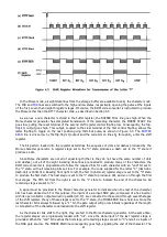
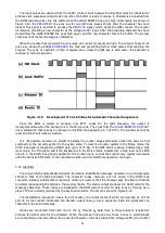
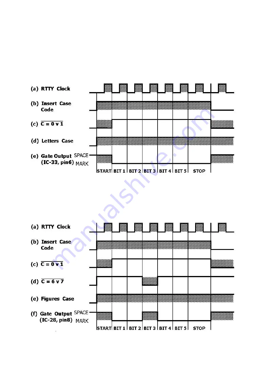
As described in Section 4.7, the RTTY control circuit detects when a change of case is necessary. In this
instance, the shift register is disabled until after the case code has been transmitted. The register output
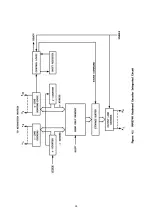
remains high during this period. Clock pulses are controlled by the logic circuit shown at the left in Figure
8.7.
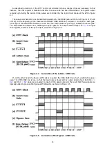
The case-code character to be transmitted is selected by the NAND gates at the far left (parts of IC's 28
and 33). At the beginning of the character the INSERT CASE CODE line, coupled to one input of each gate,
goes high. If the letter-shift character is to be sent, the LTRS CASE bus goes high, enabling the lower gate.
The FIGS CASE line remains low, disabling the upper gate, so its output remains high. The
C = 0v1
signal
then appears, inverted, at the gate output, as shown in Figure 4.4.
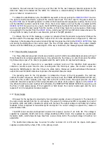
Figure 4.4 Generation of the Letters - Shift Code
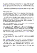
If, on the other hand, the figures-shift code is required, the FIGS CASE line is high, enabling the upper
gate. The LTRS CASE line is low, so that the lower gate is closed and its output remains high. Both the
c =
0v1
and the
C = 6v7
signals are coupled to inputs of the upper gate with the result that these signals are
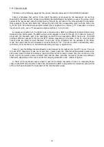
logically added to produce the figures-shift character, as shown in Figure 4.5.
Figure 4.5 Generation of the Figures - Shift Code
Summary of Contents for DKB-2010
Page 1: ......
Page 20: ...18...
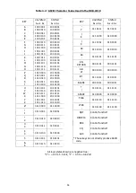
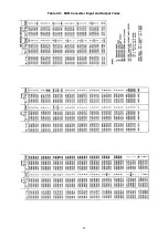
Page 39: ...37 Table 4 3 ROM Converter Input and Output Codes...
Page 52: ...50 Figure 6 1 Logic Circuit Board Test Points...
Page 53: ...51 Figure 6 2 Keyswitch Circuit Board Test Points...
Page 54: ...52 Figure 6 3 Power Supply Circuit Board Test Points...
Page 57: ...55 Table 6 4 DKB 2010 Wire List...
Page 63: ...61...
Page 64: ...62...
Page 65: ...63...
Page 67: ...65...
Page 69: ...67...
Page 71: ...69...
Page 73: ...71...
Page 75: ...73...
Page 77: ...75...
Page 79: ...77...
Page 81: ...79...
Page 83: ...81...
Page 85: ...83...
Page 87: ...85...
Page 89: ...87...
Page 91: ...89...
Page 92: ...90...
Page 93: ...91...
Page 94: ...92...
Page 95: ...93...
Page 96: ...A1 EXTENDED MEMORY OPTION FOR THE DKB 2010 KEYBOARD INSTRUCTION MANUAL...
Page 100: ...A5...
Page 101: ...A6...


