38
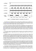
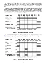
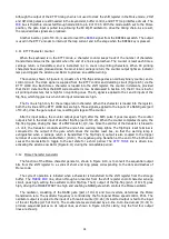
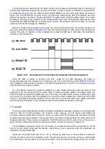
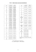
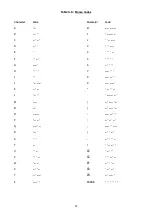
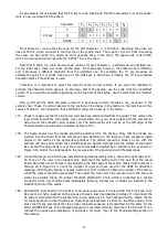
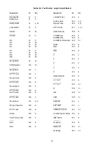
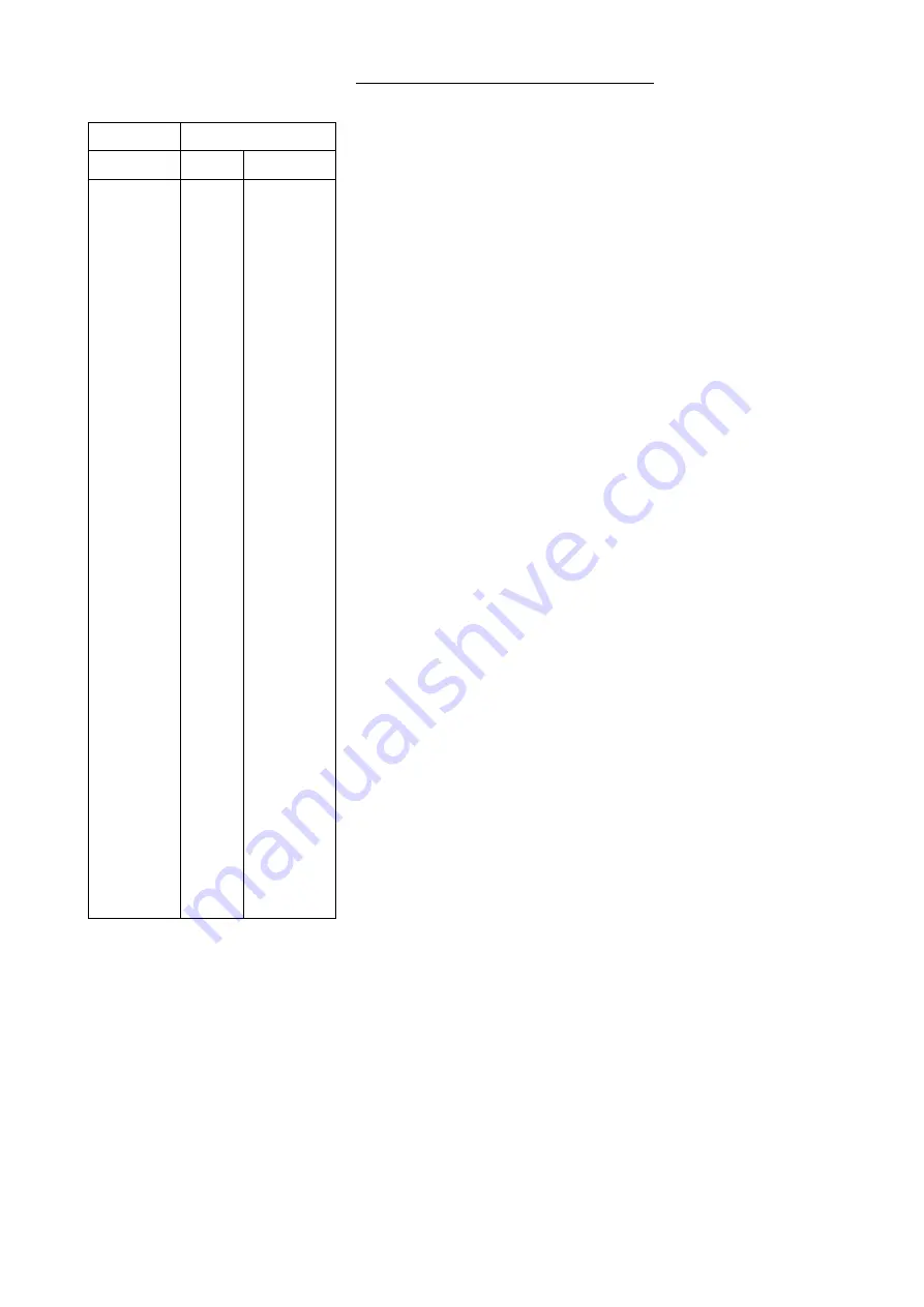
Table 4.4: RTTY Baudot Code (Military Standard)
Bit Number
Case
5 4 3 2 1
Letters
Figures
0 0 0 0 0
0 0 0 0 1
0 0 0 1 0
0 0 0 1 1
0 0 1 0 0
0 0 1 0 1
0 0 1 1 0
0 0 1 1 1
0 1 0 0 0
0 1 0 0 1
0 1 0 1 0
0 1 0 1 1
0 1 1 0 0
0 1 1 0 1
0 1 1 1 0
0 1 1 1 1
1 0 0 0 0
1 0 0 0 1
1 0 0 1 0
1 0 0 1 1
1 0 1 0 0
1 0 1 0 1
1 0 1 1 0
1 0 1 1 1
1 1 0 0 0
1 1 0 0 1
1 1 0 1 0
1 1 0 1 1
1 1 1 0 0
1 1 1 0 1
1 1 1 1 0
1 1 1 1 1
BLANK
E
LF
A
SPACE
S
I
U
CR
D
R
J
N
F
C
K
T
Z
L
W
H
Y
P
Q
O
B
G
FIGS
M
X
V
LTRS
BLANK
3
LF
-
SPACE
BELL
8
7
CR
$
4
'
,
!
:
(
5
"
)
2
#
6
Ø
1
9
?
&
FIGS
.
/
;
LTRS
Notes:
1 = mark
0 = space
LF denotes line feed
CR denotes carriage return
The order of transmission is bit 1 to bit 5. A start bit
(logical "0") precedes bit 1 and 1 to 2 stop bits
(logical "1") follow bit 5.
Figures case H is the STOP character in Military
Standard Baudot Code. The # character is used by
the HAL Visual Display System to indicate the STOP
code.
Summary of Contents for DKB-2010
Page 1: ......
Page 20: ...18...
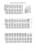
Page 39: ...37 Table 4 3 ROM Converter Input and Output Codes...
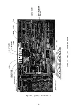
Page 52: ...50 Figure 6 1 Logic Circuit Board Test Points...
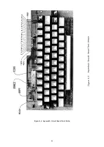
Page 53: ...51 Figure 6 2 Keyswitch Circuit Board Test Points...
Page 54: ...52 Figure 6 3 Power Supply Circuit Board Test Points...
Page 57: ...55 Table 6 4 DKB 2010 Wire List...
Page 63: ...61...
Page 64: ...62...
Page 65: ...63...
Page 67: ...65...
Page 69: ...67...
Page 71: ...69...
Page 73: ...71...
Page 75: ...73...
Page 77: ...75...
Page 79: ...77...
Page 81: ...79...
Page 83: ...81...
Page 85: ...83...
Page 87: ...85...
Page 89: ...87...
Page 91: ...89...
Page 92: ...90...
Page 93: ...91...
Page 94: ...92...
Page 95: ...93...
Page 96: ...A1 EXTENDED MEMORY OPTION FOR THE DKB 2010 KEYBOARD INSTRUCTION MANUAL...
Page 100: ...A5...
Page 101: ...A6...

