46
Symptom: Keyboard dead in both modes; does not key transmitter, sidetone oscillator or teleprinter loop
Suggested Tests:
Switch the keyboard on by rotating the volume control clockwise. If the pilot lamp does not light,
check that the keyboard is plugged into a live outlet delivering 105 to 125 V AC (or 210 to 250 V AC if
your unit is wired for nominal 230 volt operation – units so wired at the factory are marked with a special
tag). Also check that a fuse of the proper size and rating (a 1/4-amp; AGC delayed type) is installed in
the fuseholder. Check the fuse with an ohmmeter to determine whether it is blown.
If the pilot lamp does light, the trouble may be in one of the two power supplies. To check them,
unplug the line cord and remove the bottom cover by removing the three screws from the rear lip and
one from the bottom lip beneath the front panel. Note that the logic circuit board is attached to this
cover. Pivot the cover away from the cabinet, being careful not to damage the wiring harness. The power
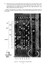
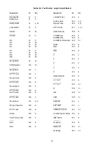
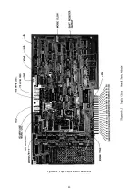
supply voltages may be checked at the locations on the logic board indicated in Figure 6.1.
Reconnect the AC line cord and switch the keyboard on. Using an accurate AC voltmeter with its
negative lead clipped to the chassis ground, measure the output of the +5 Volt supply at the position
shown. It should be within ±0.1 Volt of +5.0 Volt DC. If not, refer to step 167 in Section 5.12 for
adjustment instructions. If the output is too high and cannot be controlled by the adjustment pot, one or
more of the regulator components may be defective. Refer to the schematic diagram shown in Figure
8.15. Check especially for a shorted pass transistor (Q201) or an open adjustment pot (P201).
If there is no output voltage, or if the voltage is too low, the transformer (T301) or rectifier diodes
may be defective. Use the meter check for voltages at the primary and secondary of the transformer.
Also check for shorts across the supply output at other points in the keyboard – on the circuit boards and
in the wiring harness. It is possible to check for shorts or overloads on the two other circuit boards by
disconnecting the edge connectors from each one in turn, observing whether the voltage returns to its
correct value. Be sure to unplug the keyboard while the connections are being changed. Note that
unplugging the power supply board will disable the supply.
Measure the –12 Volt supply at the point shown in Figure 6.1. It should read between –10.5 and –
13.5 Volt. If the output is more negative than –13.5 Volt, the pass transistor (Q205) may be shorted or
the zener diodes (D202 and D203) may be open. If no voltage is present or if the voltage is too low,
check for a defective transformer (T302), blown diode or shorted capacitor. As before, the other circuit
boards can be disconnected one at a time to see whether the voltage returns to normal.
If both supplies are functioning properly, set the MODE switch to 60 WPM or to MORSE and check the
timing signals. Using an oscilloscope, observe the waveform at the point marked HØ in the diagram. It
should be a squarewave with a frequency of approximately 23 kHz generated by the timing circuitry
shown in Figure 8.8. If it is not present, the crystal, the oscillator circuit (IC-29), the control gate (parts
of IC-35 and IC-30), or one of the two divide-by-16 circuits (IC's-38 and 39) may be defective. The
oscillator output, at a frequency of about 6 MHz, should be observable at pin 12 of IC-29 and at pin 4 of
IC-30, assuming that the oscilloscope has a vertical amplifier bandwidth of at least 6 MHz.
If the oscillator is working but the HØ clock signal is not present, check the VHØ clock waveform at
the point indicated in Figure 6.1. It should be a squarewave with a frequency of about 372 kHz. If
present, the difficulty is in the second divider (IC-38).
Once it has been determined that the power supplies and timing circuits are functioning properly, the
next point to check is the output of the shift register, shown in Figure 8.6. Connect an oscilloscope to pin
10 of IC-10, the output of the last stage of the shift register, designated as "shift register output" in
Figure 6.1. Be careful not to short to adjacent pins or conductors.
When the keyboard is idling, the shift register output should be "low" – less than 0.8 Volt. Now set
the keyboard to the 60 WPM mode and press the "F" key. A series of mark and space pulses should be
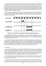
produced, as illustrated by the bottom trace in Figure 4.2 (page 24). The space pulses should be +2.4
Volt or greater. If the logic state of this output does not change, the keyencoder, ROM, buffer, shift
register, or the associated control circuits is not operating properly. To conduct more extensive testing,
press the QBF key – a long string of pulses should result (RTTY mode only).
Summary of Contents for DKB-2010
Page 1: ......
Page 20: ...18...
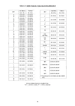
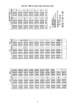
Page 39: ...37 Table 4 3 ROM Converter Input and Output Codes...
Page 52: ...50 Figure 6 1 Logic Circuit Board Test Points...
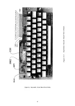
Page 53: ...51 Figure 6 2 Keyswitch Circuit Board Test Points...
Page 54: ...52 Figure 6 3 Power Supply Circuit Board Test Points...
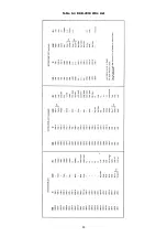
Page 57: ...55 Table 6 4 DKB 2010 Wire List...
Page 63: ...61...
Page 64: ...62...
Page 65: ...63...
Page 67: ...65...
Page 69: ...67...
Page 71: ...69...
Page 73: ...71...
Page 75: ...73...
Page 77: ...75...
Page 79: ...77...
Page 81: ...79...
Page 83: ...81...
Page 85: ...83...
Page 87: ...85...
Page 89: ...87...
Page 91: ...89...
Page 92: ...90...
Page 93: ...91...
Page 94: ...92...
Page 95: ...93...
Page 96: ...A1 EXTENDED MEMORY OPTION FOR THE DKB 2010 KEYBOARD INSTRUCTION MANUAL...
Page 100: ...A5...
Page 101: ...A6...


