47
If the shift register output is satisfactory, the difficulty must either be a result of incorrect connection
to the external equipment (RTTY loop and CW transmitter) or must result from a failure of both the RTTY
encoder and loop interface circuit (Figure 8.7) and the Morse circuitry, consisting of the Morse character
generator (Figure 8.10) and the Morse output control (Figure 8.11).
Symptom: Keyboard will not operate at any RTTY speed; O.K. in Morse mode
Suggested Tests:
Since the keyboard operates in the Morse mode, it may be assumed that the power supplies are
operating normally. The 60 WPM oscillator, its control gate, and the first two divide-by-16 counters in the
timing chain must also be working properly.
First, determine whether the external RTTY loop is in the mark (current flowing) or space (current
interrupted) state. If in the mark state, press the keyboard BREAK key. If the loop connections are
correct and if the Loop interface circuitry (Figure 8.7) is operating properly, the loop current will be
interrupted. If not recheck the loop connections; then check for a shorted switching transistor (Q2) ,
diode (D7) or capacitor (C301).
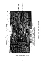
If the loop circuit remains in the space state, check the waveform at the VHØ line (indicated in Figure
6.1). It should be a squarewave of about 400 kHz. If this signal is not present, the switching transistor
(Q2) cannot be driven into conduction. Check the oscillator, control gate, and first divider circuits in the
RTTY timing chain (Figure 8.8).
The RTTY control and decoding circuit (described in Section 4.7 and illustrated in Figure 8.5) is also
unique to the RTTY mode and should be checked if the keyboard fails in the RTTY mode only. Use the
waveforms in Section IV for comparison to those observed in the unit under test.
Symptom: Keyboard fails to operate at one RTTY speed; O.K. at other speeds and in the Morse Mode
Suggested Test:
This failure will most likely be caused by a malfunction of one of the oscillators. Referring to Figure
8.8 for pin connections, check the output of each oscillator with an oscilloscope or wavemeter. The
oscillator using crystal X1 is used for 60 WPM operation, X2 for 66 WPM, X3 for 75 WPM, and X4 for 100
WPM. Set the MODE switch to the malfunctioning speed and check the oscillator signal after it has
passed through the appropriate control gate for that speed. If a defective oscillator circuit is discovered,
it is possible to substitute the crystal from one of the working oscillators. In this way one can determine
whether the crystal or the oscillator IC is at fault.
Symptom: Keyboard fails to operate in Morse mode; O.K. at all RTTY speeds
Suggested Test:
First, recheck the connections to the transmitter being keyed. If these are correct, the difficulty will
most likely be found in the Morse character generator (Figure 8.10) or the Morse output control (Figure
8.11). The performance of the latter circuit may be checked by pressing the BREAK key. With the
transmitter in the "key open" condition, pressing the BREAK key should close the circuit, putting the
transmitter into the "key closed" condition and should key the sidetone oscillator. If it does not, the
switching transistor (Q5) may be open or one of the external connections to the output jack may be
incorrect.
If the transmitter remains locked in the "key closed" condition, check for a short or reversed polarity
of the connections to the transmitter. If they are satisfactory, check for a shorted switching transistor
(Q5), protection diode (D10), or bypass capacitor (C302 and C303).
Summary of Contents for DKB-2010
Page 1: ......
Page 20: ...18...
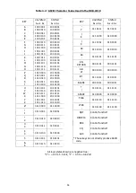
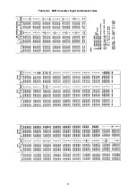
Page 39: ...37 Table 4 3 ROM Converter Input and Output Codes...
Page 52: ...50 Figure 6 1 Logic Circuit Board Test Points...
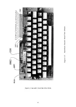
Page 53: ...51 Figure 6 2 Keyswitch Circuit Board Test Points...
Page 54: ...52 Figure 6 3 Power Supply Circuit Board Test Points...
Page 57: ...55 Table 6 4 DKB 2010 Wire List...
Page 63: ...61...
Page 64: ...62...
Page 65: ...63...
Page 67: ...65...
Page 69: ...67...
Page 71: ...69...
Page 73: ...71...
Page 75: ...73...
Page 77: ...75...
Page 79: ...77...
Page 81: ...79...
Page 83: ...81...
Page 85: ...83...
Page 87: ...85...
Page 89: ...87...
Page 91: ...89...
Page 92: ...90...
Page 93: ...91...
Page 94: ...92...
Page 95: ...93...
Page 96: ...A1 EXTENDED MEMORY OPTION FOR THE DKB 2010 KEYBOARD INSTRUCTION MANUAL...
Page 100: ...A5...
Page 101: ...A6...

