


USER OPERATION AND MAINTENANCE
HP SERIES
PORTABLE PUMPS
15
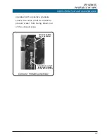
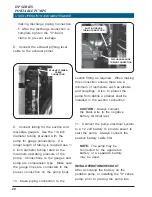
the handle must be held in the down
position until the pump is primed.
Once the pump is primed and
pressure is showing on the discharge
pressure gauge the "T" handle is
released and returns to the up
position by spring force for normal
pump operation.
The base "I" version uses a knob
(located above the throttle control)
which is pulled to engage the primer.
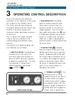
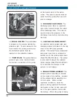
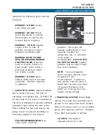
5.
SUCTION GAUGE:
The suction
gauge is located in the center of the
instrument panel and provides the
operator with an indication of the
water pressure on the suction side of
the pump. The suction gauge is a
compound gauge that reads from -1
to 10 BAR (30 in. Hg vac to 150 PSIG).
6.
LOW OIL PRESSURE LIGHT (
):
The low oil pressure light is located to
the right of the discharge gauge and
is connected to the oil pressure
switch located on the oil filter
adapter. When the master switch is
first energized the low oil pressure
light will light to indicate the pump
power is on. After the pump starts
and oil pressure builds up the light will
go out to indicate there is sufficient
oil pressure in the engine. The engine
is equipped with an oil pressure
switch that activates the low oil
pressure light when pressure drops to
0.2-0.4 kg/cm
2
(4-6 PSIG). If the light
should light during normal operation
the operator must shutdown the
engine immediately to avoid engine
d a m a g e .
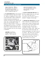
7.
CHOKE CONTROL (
):
The choke
control is located below the oil light
and is used to control the air fuel
mixture in the carburetor when
starting the engine. Pulling the choke
control out will engage the choke.
After the pump starts pushing in on
the choke control will gradually
disengage the choke and allow
normal operation.
8.
DISCHARGE GAUGE:
The
discharge gauge is located to the
right of the priming lever and
provides the operator with an
indication of the pump discharge
pressure. The gauge reads from 0 to
28 BAR (0 to 400 PSIG).
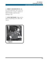
9.
FUEL PRIMER:
The fuel primer is
located on the back side of the
pump engine behind the protective
cover of the HP series pumps. The
fuel system requires priming only
when starting the pump after fuel is
put into the tank initially or if the
pump has run out of fuel. Priming is
accomplished by squeezing the fuel
primer bulb until firm.
Summary of Contents for HP 400
Page 2: ...HP SERIES PORTABLE PUMPS USER OPERATION AND MAINTENANCE 2...
Page 4: ...HP SERIES PORTABLE PUMPS USER OPERATION AND MAINTENANCE 4...
Page 44: ...HP SERIES PORTABLE PUMPS USER OPERATION AND MAINTENANCE 44 X Series Pump Mounting Dimensions...
Page 48: ...HP SERIES PORTABLE PUMPS USER OPERATION AND MAINTENANCE 48 I Series Pump Dimensions...
Page 72: ......


