Page
39
SmartFOAM
FOAM CONCENTRATE DISCHARGE HOSE
The system installer must supply fittings and hoses from
the foam pump inject connection to the check valve/injec-
tor fitting inlet. All components selected transfer foam con-
centrate, therefore they must be compatible with the foam
concentrates being used in the system.
The foam pump discharge connection is a 1/2-in (13 mm)
compression fitting. The check valve injector fitting con-
nection has 1/2-in NPT threads. Hoses and fittings of
1/2-in minimum diameter rated at 500 PSI (34.5 BAR)
working pressure or maximum discharge pressure of the
fire pump must be used. Fittings and hoses must be com-
patible with all foam agents to be used.
Recommended components
Hose:
Aeroquip 2580-8 or Equivalent Reinforced Hy-
draulic Hose.
Fittings:
Brass or Stainless Steel Hose End Crimp or Re-
usable Type (Aeroquip 412-9-8 or Equivalent).
Note: Although air brake tubing has been used for foam
concentrate discharge hose, it is not as flexible as the hy-
draulic hose and readily kinks during installation.
Additionally, the air brake tubing may not meet NFPA 500
PSI (34 BAR) test requirements.
FOAM CONCENTRATE BYPASS HOSE
The foam concentrate bypass hose connection is a 1/2-in
(13 mm) hose barb connection. Hoses and fittings of nomi-
nal 1/2-in diameter must be used as bypass hose. Since
the bypass hose is used for calibration and draining the
system it does not see high operating pressures; therefore,
a hose with a lower pressure rating than the inject hose
may be used.
Dual foam systems will each require their
own bypass connection.
Fittings and hoses used must be compatible with all foam
agents expected to be used. Use fittings made of brass or
300 series stainless steel compatible with all foam concen-
trates.
Recommended components
Hose:
Low Pressure Hydraulic Hose or Air Brake Tub-
ing.
Fittings:
Brass or Stainless Steel.
It is recommended that the foam concentrate bypass hose
be long enough to extend past the apparatus running
board to reach five (5) gallon (19 liter) containers, making
foam pump setup and calibration simpler.
CHECK VALVES
Check valves must be installed on the apparatus with foam
systems to prevent contamination of the foam concentrate
with water and contamination of the fresh water tank with
foam. When a Hale SmartFOAM foam Injection system and
related components are properly installed the required check
valves are integral parts of the system.
NFPA standards require a check valve in the foam concen-
trate injection line at the injection point. The Hale part num-
ber 038-1790-00-0 Integral Check Valve/ Injector Fitting, a
standard component included with the Hale SmartFOAM
system and installed when a manifold kit is ordered, meets
these requirements and threads directly into the foam injec-
tion port on Hale manifolds.
When dual foam units are being installed, each foam pump
must have its own injector valve installed on the manifold.
Depending on the type of dual pump system, the injection
point will vary. See “Dual Pump Foam Systems” section.
Check valves must be installed in all water piping locations
where foam concentrate could drain back into pumps or
other components of the fire apparatus.
As a minimum one check valve must be installed where the
water piping that supplies foam solution connects to the fire
pump discharge. To more effectively keep foam contamina-
tion out of the fire pump and water tank, double check
valves are recommended.
Separate two check valves by at least 6 to 8-in (152 to
203 mm) of piping to form a dead zone between the check
valves. Individual drain lines should be used on each check
valve. The waterway check valves must be rated for
500 PSIG (34.5 BAR) test pressure.
FLUSHING WATER HOSE
Flushing water connections for the Hale ADT, MDT II or
MST require using 1/2-in (13 mm) inside diameter tubing
and appropriate fittings. The tubing and fittings used must
be capable of withstanding the maximum fire pump dis-
charge pressure (500 PSI [34 BAR] minimum) and must be
compatible with foam concentrates being used in the sys-
tem.
When the ADT, MDT II or MST is installed, a check valve is
used integral to the flushing water line connection. This pro-
vides protection against water system contamination with
foam concentrate.
When dual foam units are being installed with 2 MDT II, 2
MSTs or 2 shut off valves, then each selector option will
need its own flushing line. The hose requirements above ap-
ply to each flush hose line.
Note: The installer/builder should provide an additional
check valve and shut-off valve where the flushing water
hose connects to the water pump.
Hale recommends the use of one of the above se-
lector options to provide foam system flushing ca-
pabilities. However, if the Hale SmartFOAM
Summary of Contents for MiniCAFS 2.1A
Page 3: ...Page 2 SmartFOAM NOTES...
Page 16: ...Page 15 SmartFOAM SYSTEM DIAGRAM Figure 6 Typical Hale SmartFOAM 2 1A and 1 7AHP System...
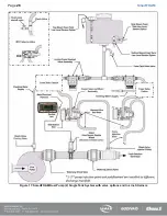
Page 17: ...Page 16 SmartFOAM Figure 7 SmartFOAM 3 3 5 0 6 5 Single Tank System with In line Strainer...
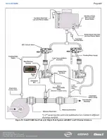
Page 18: ...Page 17 SmartFOAM Figure 8 SmartFOAM 3 3 5 0 6 5 Single Tank withMSTandIn lineStrainer...
Page 19: ...Page 18 SmartFOAM Figure 9 SmartFOAM 3 3 5 0 6 5 Single Tank withMSTandFSSeriesStrainer...
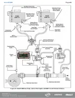
Page 20: ...Page 19 SmartFOAM Figure 10 SmartFOAM 3 3 5 0 6 5 Dual Tank withMDTIIandIn lineStrainers...
Page 21: ...Page 20 SmartFOAM Figure 11 SmartFOAM 3 3 5 0 6 5 Dual Tank withMDTIIandFSSeriesStrainer...
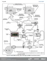
Page 22: ...Page 21 SmartFOAM Figure 12 SmartFOAM 3 3 5 0 6 5 Dual Tank withADTandIn lineStrainers...
Page 23: ...Page 22 SmartFOAM Figure 13 SmartFOAM 3 3 5 0 6 5 Dual Tank withADTandFSSeries Strainers...
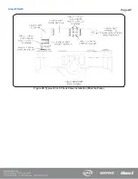
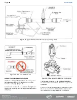
Page 48: ...Page 47 SmartFOAM Figure 28 Typical 4 Inch Check Valve Installation Midship Pump...
Page 59: ...Page 58 SmartFOAM Figure 43 ADT Option Air Hose Connections Part 2...
Page 68: ...Page 67 SmartFOAM Figure 55 Top Mount Low Level Sensor Assembly...
Page 77: ...Page 76 SmartFOAM NOTES...
Page 90: ...89 Page 89 SmartFOAM NOTES...

