Page
61
SmartFOAM
CONTROLLER UNIT POWER AND GROUND
CONNECTIONS
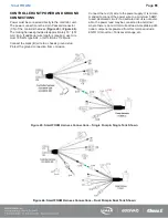
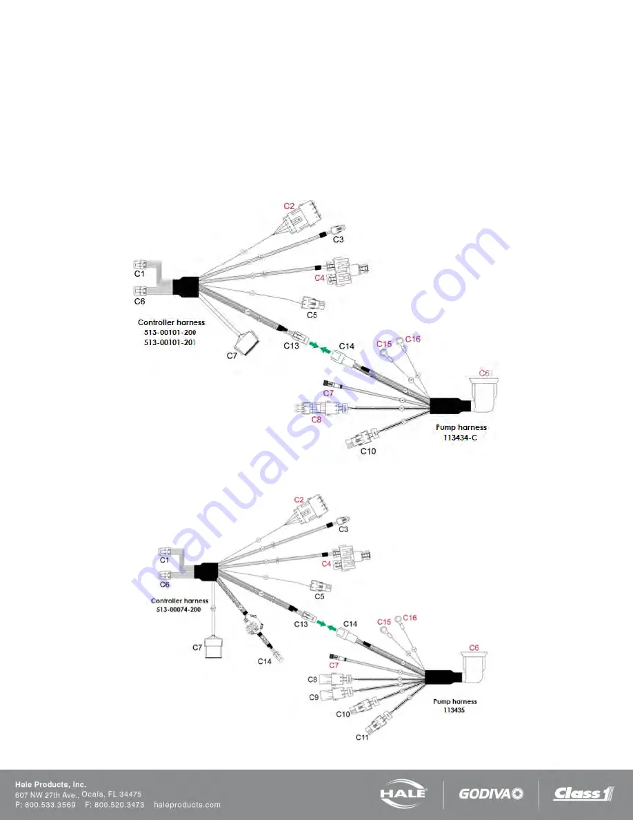
Power must be connected directly to the controller unit.
The power connection is the 2-pin Packard connector
(C5) of the controller harness (
The mating harness provided is approximately 18” (457
mm) long. If additional wire length is required, use mini-
mum 16 AWG type SXL, or GXL (SAE J1128) wire.
Connect the black (B) wire to a chassis ground stud.
Protect the ground connection from corrosion.
Connect the red (A) wire to the power supply. It is recom-
mended to connect the power wire to a minimum 5 AMP,
fused, dedicated circuit. If a dedicated circuit is not avail-
able, the power lead may be connected to a terminal
where there is not a HIGH current load. Acceptable addi-
tional components powered from this terminal include
ENFO IV, Governor, Tank Level Gauge, etc.
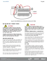
Figure 45: SmartFOAM Harness Connections – Single Pump & Single Tank Shown
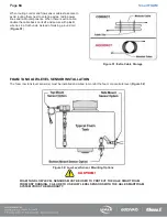
Figure 46: SmartFOAM Harness Connections – Dual Pump & Dual Tank Shown
Summary of Contents for MiniCAFS 2.1A
Page 3: ...Page 2 SmartFOAM NOTES...
Page 16: ...Page 15 SmartFOAM SYSTEM DIAGRAM Figure 6 Typical Hale SmartFOAM 2 1A and 1 7AHP System...
Page 17: ...Page 16 SmartFOAM Figure 7 SmartFOAM 3 3 5 0 6 5 Single Tank System with In line Strainer...
Page 18: ...Page 17 SmartFOAM Figure 8 SmartFOAM 3 3 5 0 6 5 Single Tank withMSTandIn lineStrainer...
Page 19: ...Page 18 SmartFOAM Figure 9 SmartFOAM 3 3 5 0 6 5 Single Tank withMSTandFSSeriesStrainer...
Page 20: ...Page 19 SmartFOAM Figure 10 SmartFOAM 3 3 5 0 6 5 Dual Tank withMDTIIandIn lineStrainers...
Page 21: ...Page 20 SmartFOAM Figure 11 SmartFOAM 3 3 5 0 6 5 Dual Tank withMDTIIandFSSeriesStrainer...
Page 22: ...Page 21 SmartFOAM Figure 12 SmartFOAM 3 3 5 0 6 5 Dual Tank withADTandIn lineStrainers...
Page 23: ...Page 22 SmartFOAM Figure 13 SmartFOAM 3 3 5 0 6 5 Dual Tank withADTandFSSeries Strainers...
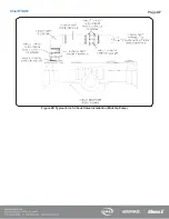
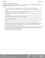
Page 48: ...Page 47 SmartFOAM Figure 28 Typical 4 Inch Check Valve Installation Midship Pump...
Page 59: ...Page 58 SmartFOAM Figure 43 ADT Option Air Hose Connections Part 2...
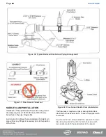
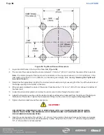
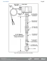
Page 68: ...Page 67 SmartFOAM Figure 55 Top Mount Low Level Sensor Assembly...
Page 77: ...Page 76 SmartFOAM NOTES...
Page 90: ...89 Page 89 SmartFOAM NOTES...

