Page
64
SmartFOAM
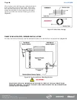
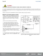
When routing control and flow sensor cables take care to
avoid routing them next to antenna wires, radio power
lines and radio components. When there is extra cable,
double the cable back on itself and secure with plastic
wire ties in a flat bundle instead of making a round coil
(
Figure 51: Extra Cable Storage
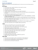
FOAM TANK LOW LEVEL SENSOR INSTALLATION
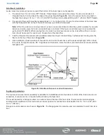
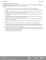
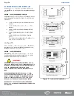
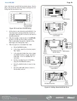
The foam low tank level sensor(s) must be installed and wired to monitor the foam concentrate level (
Figure 52: Low Level Sensor Mounting Options
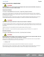
CAUTION!
FOAM TANK LOW LEVEL SENSORS MUST BE USED TO PROTECT THE HALE SMARTFOAM
FROM DRY RUNNING. FAILURE TO USE LOW LEVEL SENSORS WITH THE HALE SMARTFOAM
SYSTEM VOIDS THE WARRANTY.
Summary of Contents for MiniCAFS 2.1A
Page 3: ...Page 2 SmartFOAM NOTES...
Page 16: ...Page 15 SmartFOAM SYSTEM DIAGRAM Figure 6 Typical Hale SmartFOAM 2 1A and 1 7AHP System...
Page 17: ...Page 16 SmartFOAM Figure 7 SmartFOAM 3 3 5 0 6 5 Single Tank System with In line Strainer...
Page 18: ...Page 17 SmartFOAM Figure 8 SmartFOAM 3 3 5 0 6 5 Single Tank withMSTandIn lineStrainer...
Page 19: ...Page 18 SmartFOAM Figure 9 SmartFOAM 3 3 5 0 6 5 Single Tank withMSTandFSSeriesStrainer...
Page 20: ...Page 19 SmartFOAM Figure 10 SmartFOAM 3 3 5 0 6 5 Dual Tank withMDTIIandIn lineStrainers...
Page 21: ...Page 20 SmartFOAM Figure 11 SmartFOAM 3 3 5 0 6 5 Dual Tank withMDTIIandFSSeriesStrainer...
Page 22: ...Page 21 SmartFOAM Figure 12 SmartFOAM 3 3 5 0 6 5 Dual Tank withADTandIn lineStrainers...
Page 23: ...Page 22 SmartFOAM Figure 13 SmartFOAM 3 3 5 0 6 5 Dual Tank withADTandFSSeries Strainers...
Page 48: ...Page 47 SmartFOAM Figure 28 Typical 4 Inch Check Valve Installation Midship Pump...
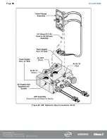
Page 59: ...Page 58 SmartFOAM Figure 43 ADT Option Air Hose Connections Part 2...
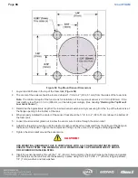
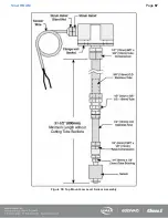
Page 68: ...Page 67 SmartFOAM Figure 55 Top Mount Low Level Sensor Assembly...
Page 77: ...Page 76 SmartFOAM NOTES...
Page 90: ...89 Page 89 SmartFOAM NOTES...

