Scope of application
Installation
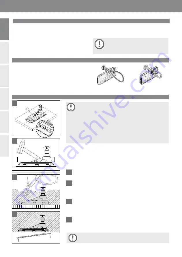
Type variants
The HALFEN HLX Lift-Box is installed in the underside
of concrete slabs (e.g. in lift shafts). It serves as an anchor-
age point for temporary suspension of objects used during
installation or maintenance.
Requirements for installation and allowable load capacities
can be found in the tables included with these installation
instructions.
Attention: The HALFEN HLX Lift-Box is not
intended for use as a personal fall protection
unit according to EN 795.
The HALFEN HLX Lift-Box must only be installed by trained
and qualifi ed personnel.
Elevator lifting device acc. to ETA-17/0488
HALFEN
LB
6
5
HALFEN
HLX Lif
t-B
o
x
1
.500
Loop
A - 5
51 - 0
5/1
7
HALFEN
LB 2.0
The use of incomplete anchors is not allowed. Missing components may
only be replaced by the manufacturer. The use of non-system compo-
nents can result in reduced safety of the unit; may also result
in anchor failure causing suspended construction elements to fall. This will en-
danger people in the vicinity and may result in serious injury or death.
The anchor system must be checked for integrity before each application.
Any change, adapting or welding to the anchor is not allowed. This may cause
the attached load to fall, resulting in injury or death. The HALFEN HLX Lift-Box
may only be used in an unmodifi ed and its original state.
Attention: The load bearing loops must not come into contact with
chemicals or other aggressive substances.
1
The correct position of the anchorage point is determined by (notches)
markings in the lid.
2
The HALFEN HLX Lift-Box can be attached with the included nails or
fi rmly glued (e.g. to steel formwork). The minimum spacings (see table 3)
must be observed. For reinforcement installation, please refer to the
section “Element requirements“.
3
The concrete must be poured and compacted carefully around the
HALFEN HLX Lift-Box. Avoid direct contact between the vibrator and the
HALFEN HLX Lift-Box components. Remove the formwork carefully to
avoid any damage.
4
Remove the lid and nails.
2
4
The HALFEN HLX Lift-Box is installed in the underside of concrete slabs
(e.g. in lift shafts).
The condition of the HALFEN HLX Lift-Box components and the concrete slab
must be visually inspected before each use. The system must be evaluated by a
qualifi ed person if there is doubt about its integrity.
1
3
The HLX Lift-Box is available in 2 types with 3 load steps:
The
HLX Loop
with wire loop or the
HLX Link
with chain
link.
Both systems are robustly built for suspending hooks, and
are folded back into the box after utilization. The installation
sequence for both variants is the same.
HALFEN
LB
HLX Lift-Box Loop
(with wire loop)
HLX Lift-Box Link
(with chain link)
2
© 2019 HALFEN · INST_HLX 10/19 · www.halfen.com
HALFEN HLX
Assembly Instructions
Deutsch
Por
tuguês
English
Fr
ançais
Italiano
Polski


