background image

2

©  2016 HALFEN · INST_AB 06/14  · www.halfen.com

Deutsch

English

Fr

ançais

Česky

DEHA 6325 

Assembly Instructions

Polski

The corresponding operating information including the installation and assembly instructions must 
be readily available in the precast plant and on site; the instructions must be observed.

DEHA Lifting loops 6325

The DEHA 6325 Lifting loops are 
used to transport precast reinforced 
concrete elements. The loop is made  
of high strength steel cable shaped to 
an oval and secured with a pressed 
ferrule. 

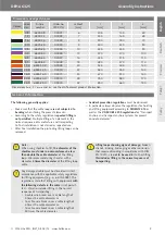
The lifting loops are identifi ed with a 
colour label marked with the name of 
the manufacturer, the year of produc-
tion and the load class (see Fig. 1). 

The load capacity must be verifi ed 
according to the specifi c require-
ments. All infl uencing coeffi

  cents 

must be considered in the calculation,
for example;
• impact factor
• diagonal pull
• adhesion factor

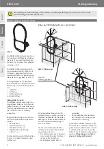
Installation (Fig. 2 and 3):

The lifting loops are always installed 
in the top accessable surface of the 
precast element. Longitudinal or 
lateral orientation is possible. The 
loop-end with the ferrule is positioned 
in the formwork. 

The following dimensions and distan-
ces must be observed during installa-
tion:
• embed depth t 
• loop projection ü 
•  minimal spacing e

Z

/2

•  minimal element thickness 

b resp. 2 × e

r

The identifi cation label on the lifting 
loop must remain visible after pouring 
the concrete.

Installation of DEHA Lifting loops in precast element

Fig. 2:  Transverse 

installation

Fig. 1

Fig. 3:  Longitudinal 

installation

30°

30°

ü

t

L

30°

30°

ü

b

t

L

e

z

/2

e

z

/2

Q-Mesh reinforcement
bent to a U-shaped

The required minimum and additional 
reinforcement must be installed acc. 
to static specifi cations. The concrete 
cover of the DEHA Lifting loop and 
the additional reinforcement must be 
in accordance with EC2.

Crane hooks can be connected 
directly to the protruding lifting loops: 
•  The bending radius of the hook 

used for lifting must be equal or 
greater than the diameter of the 
cable.

•  Sharp-edged hooks must be 

avoided. 

•  The allowable maximum spread 

angle is 60°, e.g. diagonal pull is 
permitted up to 30°.

If the DEHA Lifting loops are installed 
in the small side of a minimal thick-
ness element, they can be orientated 
either parallel (fi g. 2) or perpendicular 
(fi g. 3); 

in this case diagonal pull at 

right angles to the walls main orien-
tation is not allowed

.

l

s

2 × e

r

l

s (Mesh)

Summary of Contents for DEHA 6325

Page 1: ...6325 INST_AB 06 14 Assembly Instructions Montageanleitung Notice d utilisation Instrukcja monta u Mont n n vod Lifting loops D CZ Lanov smy ky PL P tle transportowe Boucles de levage F Abhebeschlaufe...

Page 2: ...le is positioned in the formwork The following dimensions and distan ces must be observed during installa tion embed depth t loop projection minimal spacing eZ 2 minimal element thickness b resp 2 er...

Page 3: ...iameter Dimensions and edge distances Colour Load class Article number Order no 0742 110 cable mm l mm t mm mm 0 8 6325 0 8 00001 6 205 145 60 1 2 6325 1 2 00002 7 230 165 65 1 6 6325 1 6 00003 8 250...

Page 4: ...der Schalung angeordnet Folgende Abmessungen und Abst n de m ssen beim Einbau eingehalten werden Einbindetiefe t Schlaufen berstand Mindestabstand eZ 2 Mindestdicken des Bauteils b bzw 2 er Die Kennze...

Page 5: ...t klasse Artikel bezeichnung Bestell Nr 0742 110 Seil mm l mm t mm mm 0 8 6325 0 8 00001 6 205 145 60 1 2 6325 1 2 00002 7 230 165 65 1 6 6325 1 6 00003 8 250 180 70 2 0 6325 2 0 00004 9 300 220 80 2...

Page 6: ...dans le co rage Les dimensions et distances suivantes doivent tre respect es lors de l installation Profondeur d ancrage t D passement de la boucle Distance minimale eZ 2 paisseurs minimales de l l m...

Page 7: ...0742 110 de c ble mm l mm t mm mm 0 8 6325 0 8 00001 6 205 145 60 1 2 6325 1 2 00002 7 230 165 65 1 6 6325 1 6 00003 8 250 180 70 2 0 6325 2 0 00004 9 300 220 80 2 5 6325 2 5 00005 10 325 235 90 4 0...

Page 8: ...a u nale y przestrzega poni szych wymiar w i odst p w g boko osadzenia t d ugo cz ci wystaj cej minimalny odst p ez 2 minimalna grubo elementu b wzgl dnie 2 x er Przywieszka identy kacyjna na p tli tr...

Page 9: ...0 165 65 1 6 6325 1 6 00003 8 250 180 70 2 0 6325 2 0 00004 9 300 220 80 2 5 6325 2 5 00005 10 325 235 90 4 0 6325 4 0 00006 12 370 270 100 6 3 6325 6 3 00007 16 425 315 110 8 0 6325 8 0 00008 18 480...

Page 10: ...p n m i pod ln m sm ru Prstenec se p ipevn v bedn n P i mont i mus b t dodr eny tyto rozm ry a vzd lenosti hloubka vetknut t p esah smy ek minim ln vzd lenost eZ 2 minim ln tlou ky d lce b p p 2 er S...

Page 11: ...c 30n sobn mu pr m ru lana Rozm ry a vzd lenosti od okraje Barva T da zat en Artikl Objednac slo 0742 110 Pr m r lana mm l mm t mm mm 0 8 6325 0 8 00001 6 205 145 60 1 2 6325 1 2 00002 7 230 165 65 1...

Page 12: ...ax 47 51823401 Poland HALFEN Sp z o o Ul Obornicka 287 60 691 Poznan Phone 48 61 6221414 E Mail info halfen pl Internet www halfen pl Fax 48 61 6221415 Sweden Halfen AB V dursgatan 5 412 50 G teborg P...

Reviews: