


3
© 2017 HALFEN · INST_HSC 10/17 · www.halfen.com
HALFEN HSC
Assembly instructions
Deutsch
English
Fr
ançais
Polski
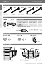
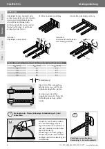
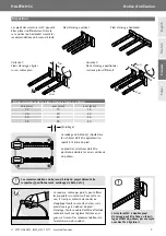
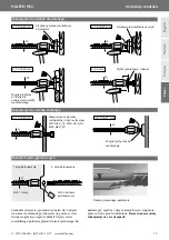
Attached to existing reinforcement,
e. g. by wire fi xing!
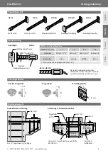
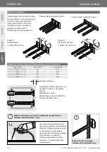
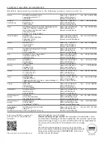
Min. distances to ensure installation (male bars)
d
HSC
[mm]
e
HSC
[mm]
a
HSC
[mm]
12
10
15
16
20
20
20
20
25
25
25
30
Stud heads can be aligned horizontal-
ly or vertically. To ensure installation
of the (male) connecting bars, mini-
mum spacing has to be maintained
(not necessary for monolithic compo-
nents). The engineer’s specifi cations
are obligatory.
e
HSC
d
HSC
Variation 1:
anchor-heads aligned in
one plane
d
HSC
a
HSC
Variation 2:
staggered HSC anchors
– minimized axial distances
Vertical anchor-head placement
Horizontal anchor-head placement
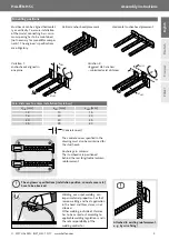
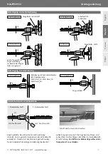
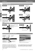
Mounting positions
The concrete cover specifi ed in the
drawing must also be maintained for
the stud heads.
Anchorage in columns:
The stud-heads are positioned
behind the rear longitudinal column
reinforcement.
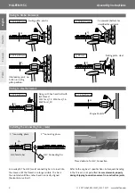
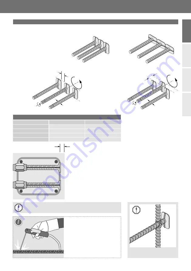
Welding, even spot welding, can
impair material properties. For that
reason welding and heat application
in the head and thread area is not
allowed.
Other welding, outside of this area
has to be carried out according to
applicable welding regulations and is
the sole responsibility of the
welding-contractor.
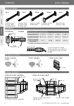
(Concrete cover)
c
i
The engineers specifi cations (installation position, concrete cover etc.)
have to be observed.


