Genesis Digital™ HDMI Matrix Switches
11
Notice about Additional
Commands
HSM matrices equipped with IP Port have
special Serial Commands to change IP
address parameters.
Please refer to section 5.3 for IP specific
serial commands.
Important Note on Control
Commands
Almost all commands issued to the Matrix
will elicit a response from the Matrix once
the command is accepted and execution
completed. After issuing any command, you
must wait for the matrix’s response prior to
sending another command. If you send
another command prior to completion of the
previous one, the matrix might ignore the
2
nd
command.
4. Control Commands (RS-232 and IP)
The Genesis™ Matrices can be controlled via an external control system by using
either the standard RS-232 or the optional IP port. Any program capable of standard
serial communication in ASCII format is capable of working with the matrix. Most PCs
with Windows™ OS have HyperTerminal™ or equivalent. There are also many free
Terminal Emulator software programs available for download on the internet.
Note on RS-232 port availability on PC
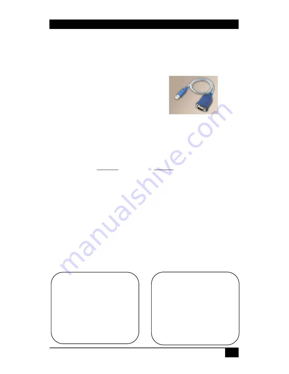
Most PCs and notebooks do not come equipped with a
serial RS-232 port. Therefore, for serial control from a
PC you may need a USB to RS-232 converter. These
are available from Hall Research (Model USB-RS232-
1).
Figure 9 – USB to RS-232 Adapter
Use a DB9 Male-to-Female cable per Table 1 to connect the unit to the PC’s serial
port.
Use 9600 Baud, 8 bits, No Parity, 1 Stop bit, No flow control.
Upon power up, the Matrix will output a screen similar to below through its serial port.
Special characters shown in <> brackets. <cr> is the carriage return character (0x0D),
<lf> is the line feed character (0x0A)
4.1 Routing Functions
NOTE: HDMI Video and Audio always routed together.
Video routing commands specified are from the point of view of the output. The
wildcard character ‘*’ is acceptable for output (but not input). In addition, these
commands can be used to monitor or query the status of system ties. Omitting the
input channel will result in a response of the current routing for that output.
3.2.2.1 To make a video tie:
COMMAND
MEANING
PW0<cr>
POWER IS OFF
CO1,1<cr>
INPUT 1 ROUTED TO OUTPUT 1
CO2,2<cr>
INPUT 2 ROUTED TO OUTPUT 2
CO3,3<cr>
INPUT 3 ROUTED TO OUTPUT 3
CO4,4<cr>
INPUT 4 ROUTED TO OUTPUT 4
HD1,0<cr>
NO VIDEO INPUT ON OUTPUT 1
HD2,0<cr>
NO VIDEO INPUT ON OUTPUT 2
HD3,0<cr>
NO VIDEO INPUT ON OUTPUT 3
HD4,0<cr>
NO VIDEO INPUT ON OUTPUT 4


