UHBX-Series
3
3.0 Setup
3.1 Package Contents
Each end is packaged separately and incudes a universal power supply (5v
DC output), and a copy of this User’s Manual.
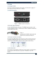
3.2 Sender Connections
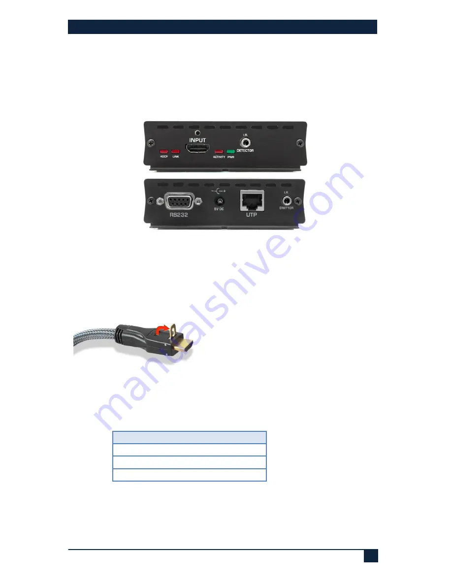
Figure 1 - UHBX-S Sender Connections
3.2.1 Sender Video Connection
Connect the HDMI input to the source. The HDMI input connector on the
box has a locking nut above it. Hall Research offers compatible locking high-
quality HDMI input cables.
Figure 2 -
Hall Research C-HDMI-L high bandwidth
HDMI cable with flip-up locking tab
3.2.2 Sender Serial Data Connection
If required, plug DB9 RS232 cable from source to the connector on the box.
Typically a straight-through male-to-female cable is used to connect to the
sender. Pin out of the RS232 connector on the sender is shown below
DB9-F Pin
Term
Direction
2
TX
Output
3
RX
Input
5
GND
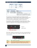
3.2.3 IR Connections
The extender can extend Infra-red Remote Control signals in both directions.
On each box two IR connectors are provided: “IR Detector” and “IR
Emitter.”


