background image


UHBX-Series 


3.2.4 UTP (Twisted Pair Catx) Connection 

The extender is designed to be used with CAT6 UTP or STP cabling. 

However, CAT5e cables may be used but the maximum cable length will be 

reduced by approximately 20% depending on the quality of the cable.  
Augmented CAT6 cables can also be used, and are recommended for 

extension distances exceeding 140 meters (or >450 feet). 
T568A termination standard is recommended for the UTP cable, However 

T568B will also work (as long as both ends are terminated the same way). 
In EMI noisy environments (such as close proximity to power transformers 

or AC wiring) shielded twisted pair (STP) cable is recommended. If STP is 

used it is important to ensure the RJ45 connector on both ends of the cable 

have the required metal shroud and that the cable shield/drain wire is 

electrically connected to the metal shroud. 

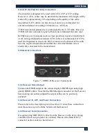
3.3 Receiver Connections 


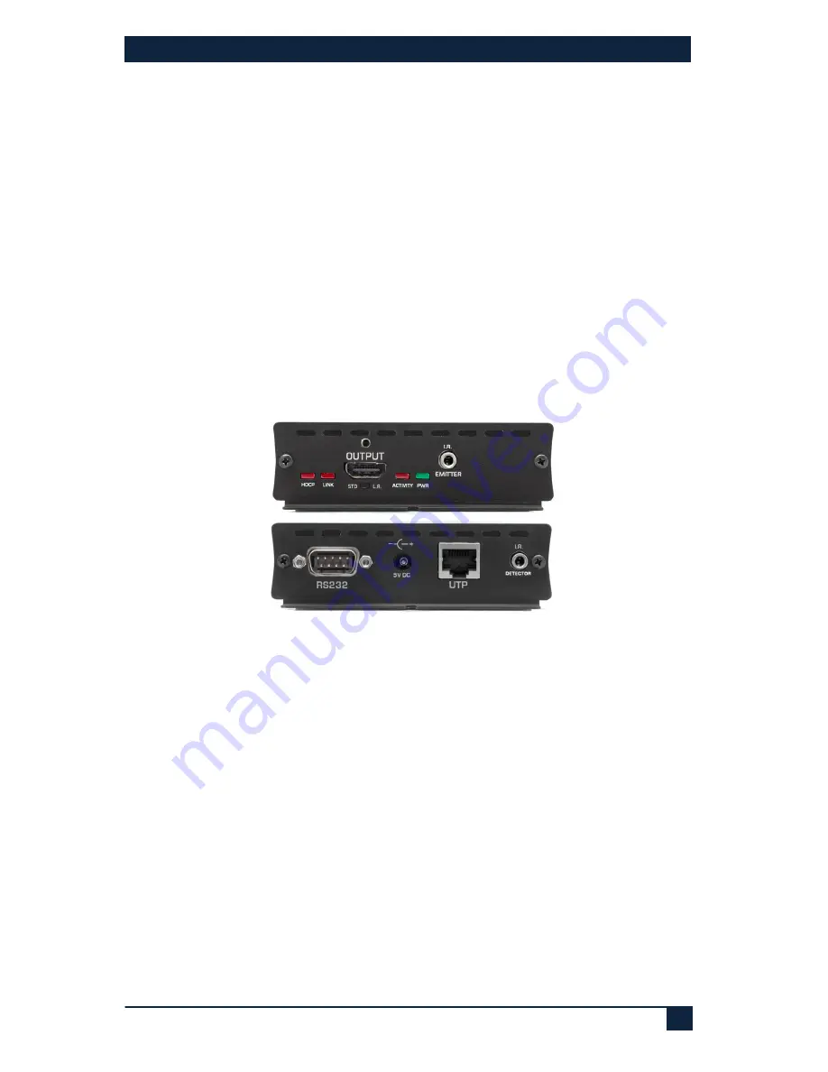
Figure 7 - UHBX-R  Receiver Connections 

3.3.1 Receiver Video Output 

Connect the HDMI output to the remote display's HDMI input using high 

quality HDMI cables. Note that the HDMI output connector on the Receiver 

has a locking nut so that compatible output cables can be positively 

anchored. 

3.3.2 Receiver IR, UTP, and Power Connections 

Please refer to the description given in section 3.2 since these connections 

work the same way on both the Sender and the Receiver.  

3.3.3 Receiver Serial Connection 

If required, plug DB9 RS232 cable from the Receiver to the device being 

controlled (such as a projector or switcher). Pinout of the Male RS232 

connector on the sender is shown below 

Summary of Contents for UHBX-S

Page 1: ...6 cable Model numbers covered in this User s Manual UMA1238 Rev 1 0 Individual Ends UHBX S HDMI RS232 IR UTP Sender UHBX R HDMI RS232 IR UTP Receiver Kits UHBX HDMI RS232 IR UTP Extender includes Send...

Page 2: ...resolutions are supported upto 1920x1200 and HDTV resolutions of UHD 4Kx2K are supported Two user selectable distance modes are available Standard and Long Reach These modes are explained further in s...

Page 3: ...high quality HDMI input cables Figure 2 Hall Research C HDMI L high bandwidth HDMI cable with flip up locking tab 3 2 2 Sender Serial Data Connection If required plug DB9 RS232 cable from source to t...

Page 4: ...esive backing Pinout Tip Anode Ring Cathode Sleeve Not Connected An alternative Emitter cable is CIR EMT2 This cable is better suited for situations where there is a need to isolate and confine the IR...

Page 5: ...nt to ensure the RJ45 connector on both ends of the cable have the required metal shroud and that the cable shield drain wire is electrically connected to the metal shroud 3 3 Receiver Connections Fig...

Page 6: ...switch located under the HDMI output connector on the Receiver Two modes are available Standard STD and Long Reach L R If the length of UTP cable is less than 100 meters 330 ft then STD mode should be...

Page 7: ...es are suited for analog video extension but do not work well for digital video Read section 3 2 4 for UTP cable requirements The extender requires that the source DDC signals of its HDMI output opera...

Page 8: ...15 200 IR Extended in both directions Modulation from 30 KHz to 60 KHz General Power Supply 100 VAC to 240 VAC 50 60 Hz external 5 VDC 2 A regulated Actual DC current Sender 0 60A approx Receiver 0 95...

Reviews: