background image


HDMI Extender with RS-232 and IR 


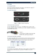
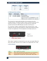
DB9-M Pin 

Term 

Direction 

RX 

Input 

TX 

Output 

GND 


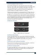
3.4 Setting the Distance Mode 

Mode 

UTP Length 

Notes 

STD 

0 to 100 m (330ft)  Default setting 

L.R. 

0 to 150 m (500ft)  Long Reach setting  

Supports maximum of 1080p@60 Hz, 8-bit. 

1080p deep-color and 4Kx2K are not supported


The extender has a mode setting that affects the maximum achievable 

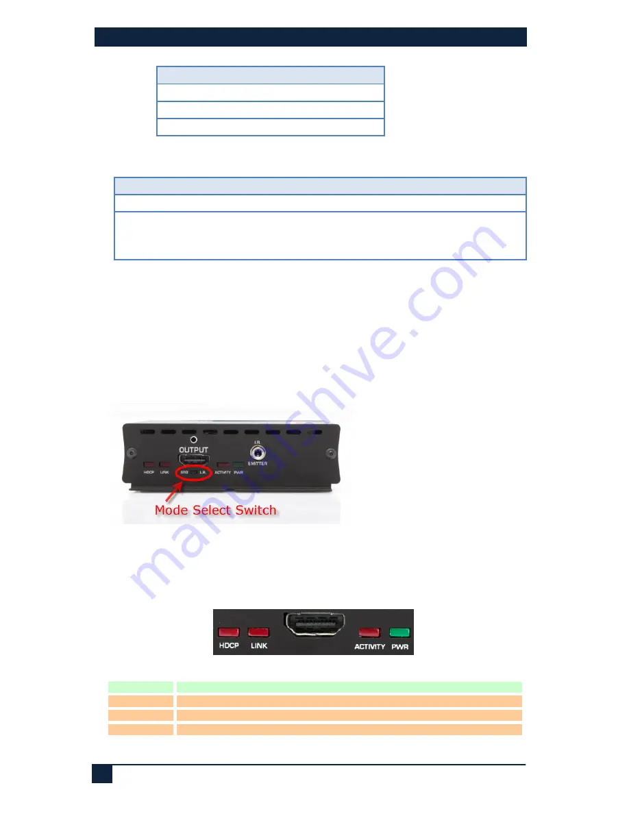
extension distance. The Distance Mode switch is located on the Receiver (the 

Sender does not have a mode switch). The mode switch is a small slide 

switch located under the HDMI output connector on the Receiver. 
Two modes are available: Standard (STD), and Long Reach (L.R.). If the 

length of UTP cable is less than 100 meters (330 ft), then STD mode should 

be used. For lengths above 330 ft Long Reach (L.R.) mode must be set. 


Figure 8 – 
Mode Switch 


When using “Long Reach” ensure that the source does not output 1080p with 

deep color nor 4K video since these formats are not supported in L.R. mode. 

3.5 LED indicators 


Figure 12 – LED Indicators 

PWR 

Power.

 Indicates unit is powered 

ACTIVITY 

Firmware Running

. Blinking means device firmware is running properly 

LINK 

UTP Link.

 Solid on means Sender & Receiver are communicating. 

HDCP 

Video Status.

 Off = No Video, Blink = Video, Solid ON = Video + HDCP 


Summary of Contents for UHBX-S

Page 1: ...6 cable Model numbers covered in this User s Manual UMA1238 Rev 1 0 Individual Ends UHBX S HDMI RS232 IR UTP Sender UHBX R HDMI RS232 IR UTP Receiver Kits UHBX HDMI RS232 IR UTP Extender includes Send...

Page 2: ...resolutions are supported upto 1920x1200 and HDTV resolutions of UHD 4Kx2K are supported Two user selectable distance modes are available Standard and Long Reach These modes are explained further in s...

Page 3: ...high quality HDMI input cables Figure 2 Hall Research C HDMI L high bandwidth HDMI cable with flip up locking tab 3 2 2 Sender Serial Data Connection If required plug DB9 RS232 cable from source to t...

Page 4: ...esive backing Pinout Tip Anode Ring Cathode Sleeve Not Connected An alternative Emitter cable is CIR EMT2 This cable is better suited for situations where there is a need to isolate and confine the IR...

Page 5: ...nt to ensure the RJ45 connector on both ends of the cable have the required metal shroud and that the cable shield drain wire is electrically connected to the metal shroud 3 3 Receiver Connections Fig...

Page 6: ...switch located under the HDMI output connector on the Receiver Two modes are available Standard STD and Long Reach L R If the length of UTP cable is less than 100 meters 330 ft then STD mode should be...

Page 7: ...es are suited for analog video extension but do not work well for digital video Read section 3 2 4 for UTP cable requirements The extender requires that the source DDC signals of its HDMI output opera...

Page 8: ...15 200 IR Extended in both directions Modulation from 30 KHz to 60 KHz General Power Supply 100 VAC to 240 VAC 50 60 Hz external 5 VDC 2 A regulated Actual DC current Sender 0 60A approx Receiver 0 95...

Reviews: