background image

EtherNet/IP adapter functionality 

11 


match those of the SMpdp module. Please note that the PLC can readout the actual size of the 
process data configured inside the KE/SE from the diagnostics area (see reference section). 

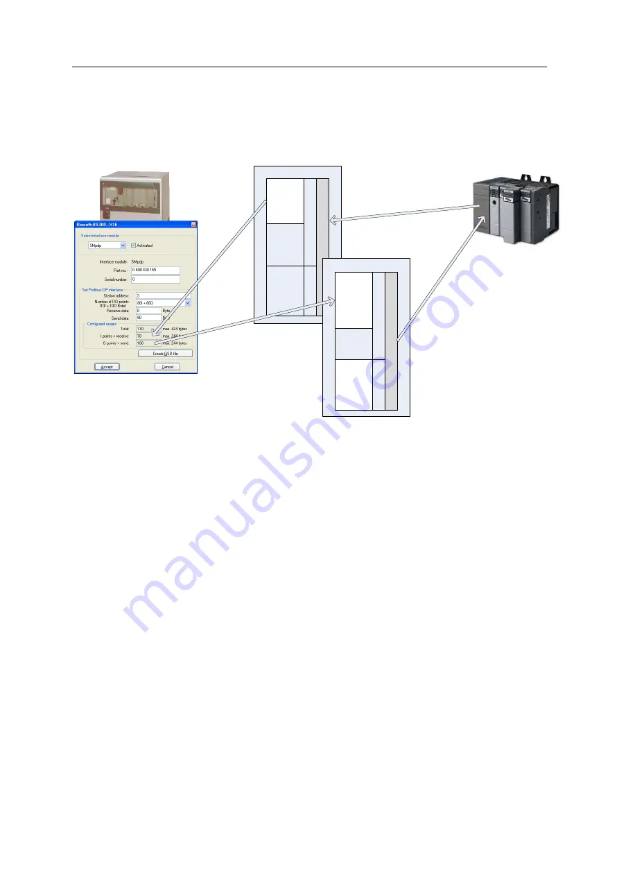
The following picture shows the data flow and data areas in an example case: 

2

4

0

 b

y

te

s

 p

ro

c

e

s

s

 d

a

ta

K

E

 in

p

u

ts

(1

0

 b

y

te

s

)

CIP object

1

4

4

 u

n

u

s

e

d

u

n

u

s

e

d

3

8

4

 b

y

te

s

 C

IP

 o

b

je

c

t d

a

ta


u

n

u

s

e

d

2

4

0

 b

y

te

s

 p

ro

c

e

s

s

 d

a

ta

K

E

 o

u

tp

u

ts

(1

0

0

 b

y

te

s

)

1

4

4

 d

ia

g

s

u

n

u

s

e

d

3

8

4

 b

y

te

s

 C

IP

 o

b

je

c

t d

a

ta


P

ro

fib

u

s


d

ia

g

n

o

s

tic

s

CIP object

Read process data

(get assembly 103 data)

Write process data

(set assembly 103 data)

PLC

BG02-EIP

SE/KE


3.2.1


Input data (PLC 

 BG02 

 KE) 

The process input data (data sent from PLC to BG02) is mapped into the lower 240 bytes of the 
assembly object instance 103 attribute 3. This data is cyclically updated (every 20ms) by writing to 
the Profibus Slave #3 (the KE/SE SMpdp interface). The PLC must always write 384 bytes. 

3.2.2


Output data (KE 

 BG02 

 PLC) 

As outlined above, the output data sent from BG02 to the PLC is made up of two blocks. The first 
block contains process data read from the KE’s SMpdp Profibus module, the second contains 
diagnostics data on the BG02 

 KE SMpdp Profibus communication. The second block always starts 

at byte offset 240 (dez), as the maximum process data size allowed in the KE is 240 Bytes. The PLC 
must always read a fixed size of 384 bytes, therefore reading both blocks of information. 

The first block containing process data is a 1:1 copy of the process data received via the Profibus 
interface from the SE/KE. This means all signal mapping is done inside the KE using the BS300 
software by setting up the “PLC assignment table”. 

The following table shows the layout of the diagnostics area. Note, that all values are encoded using 
“intel” endianness (“little endian”, i.e. LSB is first in memory). 

Summary of Contents for BG02-EIP

Page 1: ...HALLER ERNE GMBH Manual BG02 EIP Ethernet IP Gateway for System 300 310 Document revision 1 3 2008 06 04 for BG02 EIP firmware V1 4...

Page 2: ...created V1 1 2008 05 19 HE Updated description for ControlLogix setup V1 2 2008 05 21 HE Added changes for firmware V1 3 V1 4 2008 06 04 HE Added changes for firmware V1 4 added some diagnostic detai...

Page 3: ...Configuration with Hilscher Sycon NET 6 2 3 2 Configuration with ControlLogix 9 3 EtherNet IP adapter functionality 10 3 1 Message Server 10 3 2 Process Data Mapping 10 3 2 1 Input data PLC BG02 KE 11...

Page 4: ...etection EtherNet IP EtherNet IP adapter device Minimal I O update rate 20ms IMpdp SMpdp Interface for SE KE tightening system IMpdp SMpdp Compatible to System 300 310 SMpdp and CS351 IMpdp Automatic...

Page 5: ...s closely to BT300 The module s power supply ensues directly via the control unit Only the data interface is accessable from the exterior 1 3 2 Connecting with the SMpdp IMpdp module Use the supplied...

Page 6: ...nected LED B SMpdp IMpdp connectivity This LED indicates the operating state of the SMpdp interface o Green blinking Everything ok data exchange running o Green Red blinking SMpdp physical connection...

Page 7: ...immediately starts to scan the network for available BG02 s and shows each BG02 found in a list see the following screenshot Note that the serial number as well as the current network settings are sho...

Page 8: ...ystem In general the tightening system requires a profibus slave card SMpdp to communicate with the BG02 EIP So the configuration of the tightening system is actually configuring the SMpdp card correc...

Page 9: ...the BG02 Start by adding the master scanner and slave BG02 EIP adapter devices Note that the BG02 must be added as ENIP generic adapter Then configure the master by double clicking the CIFx 50 icon N...

Page 10: ...e you can setup which IP addresses the scanner should actually scan i e the IP addresses You should modify the IP address so it matches the actual IP address of the BG02 Press OK to finish the masters...

Page 11: ...ameters Make sure to set all parameters exactly as show in the following screenshot The last step is to define the process data access paths The BG02 EIP provides all process data in assembly instance...

Page 12: ...will match exactly the definitions as outlined above The only exceptions are the Assembly Instances for Input and Status Input if configured The ControlLogix does not strip off the 32 bit header in f...

Page 13: ...s defined by the standard The size of the attribute data is fixed 384 bytes for reading and writing The actual size of the process data image is defined in the KE s PLC assignment table and copied int...

Page 14: ...updated every 20ms by writing to the Profibus Slave 3 the KE SE SMpdp interface The PLC must always write 384 bytes 3 2 2 Output data KE BG02 PLC As outlined above the output data sent from BG02 to th...

Page 15: ...Timeout counter incomplete response from slave 274 2 SINT iCntPktEFrame count of illegal packets received framing error 276 2 SINT iCntPktECRC count of illegal packets received checksum errors 278 2 S...

Page 16: ...reen red or it blinks red 2 After the Profibus is stopped the SE KE s SMpdp waits for the Profibus watchdog to timeout about 500ms After the timeout the system error signal of the tightening system is...

Page 17: ...start of the next cycle The following picture shows the general timing of both busses the internal buffers are in light red the data on the busses in olive out in out in in out out in in out TPDPcyc...

Page 18: ...x 5ms 45ms Ttotal 105ms 4 2 EtherNet IP CIP Object Classes 4 2 1 Identity Object Class Class code 0x01 The identity object provides the following attributes Attribute ID Access Name Data type Value 1...

Page 19: ...By reading it process output data from the KE is returned reading signals as well as status data By writing it process output data is transmitted to the KE setting signals 4 2 4 Connection Manager Obj...

Reviews: