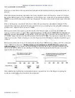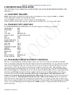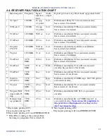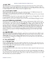
REPAIR AND RESTORATION OF THE SR-400
10
WDØGOF 6/22/20014
2. RECEIVER FAULT ISOLATION
YOU MUST HAVE ALL THE OSCILLATORS TESTED AND ALIGNED BEFORE PROCEEDING. SEE
SECTION 1-5.
2-1. EQUIPMENT REQUIRED.
HF RF signal generator capable of 0.5 microvolts to 300 millivolts and covering 1600 KHZ to 30 MHZ
Audio output meter (similar to General Radio 1840A).
Scope 100 MHZ or better with 1:1 and 10:1 probes or switchable probe.
Audio oscillator with 600 ohm output Z
0
capable of from 0.4 millivolts to 30v peak to peak output.
2-2. STANDARD TEST CONDITIONS
For the RECEIVER FAULT ISOLATION tests the following preset conditions are required.
OPERATION
REC
FUNCTION
LSB
CAL
OFF
CAL ADJ
MID RANGE
MAIN TUNING
250 (BLACK SCALE)
CW
OFF
NOTCH
CCW
BAND SELECTOR 7.0
PRESELECTOR
40
AF GAIN
MAX
RF GAIN
MAX
NOISE BLANKER OFF
METER
RFO/S
RF LEVEL
CCW
MIC GAIN
CCW
RIT
OFF
RIT CONTROL
MID RANGE
LOAD & PLATE
N/A
2-3. PROCEDURE OVERVIEW & PRESET CONDITIONS
This test is a standard progression from output to input of a receiver. It assumes the probability of multiple
faults. At any point in the procedure if a fault is detected it must be cleared before you can go the next step. The
signal levels were derived from years of testing. The levels are not absolute in that an individual receiver may
vary as much as 10%. Any deviation of more than that should be considered a fault. AGC problems can be
difficult to localize particularly if there are other faults in the system. So for the 13 step FAULT ISOLATION
procedure that follows we will disable the agc. Locate the junction of R42 and R123. Place a clip lead from that
junction to ground. Once the fault isolation is complete and the receiver is working properly tests of the agc
circuit will be performed.
A 10:1 scope probe will be used to inject signals. Some measurements will
require a 1:1 scope probe and these measurements will be noted
. The signal levels on the chart are injected
signal levels therefore,
when using the 10:1 probe the source will be set for 10 times
the level stated in the
chart. The first two audio signals are measured peak to peak using a tee connector on the audio oscillator. One
side of the tee connects directly to the scope the other to the 1:1 injection probe. The remaining signals are RMS
values as set on the RF signal generator output meter.
NOTE:
Section 4 contains individual ckt and sub-ckt
fault isolation tests.

